3-3 Maintenance after Network Configuration
3-3-2 Editing the FINS Local Network Tables
Note
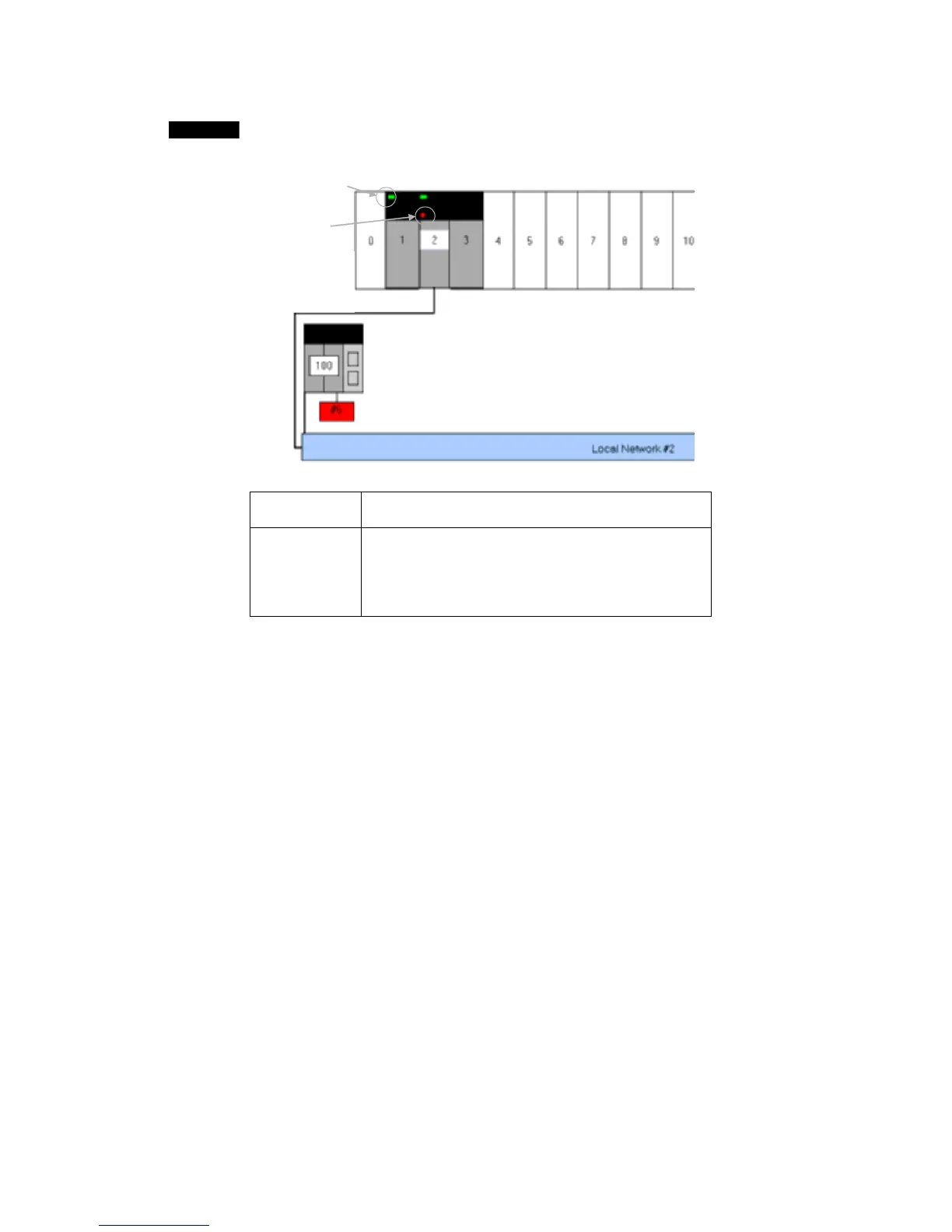
When the PLC is connected online, the display will show green and red indicators on
the Units that indicate errors with Units registered in the routing tables.
Note: These
indicators are
not related to
the actual LED
Indicators on
Red Indicator:
Error with Unit
Green Indicator:
Unit exists in routing
tables.
The following table shows the meaning of the display's indicators.
Green indicator The Unit with the unit number set in the routing tables is
actually mounted in the PLC Backplane.
Red indicator One of the following errors was detected in the Unit with the
unit number set in the routing table.
1. The Unit's node address is duplicated.
2. The Unit's node address is out-of-range.
3. There is an error in the routing table settings.
3-26
 Loading...


