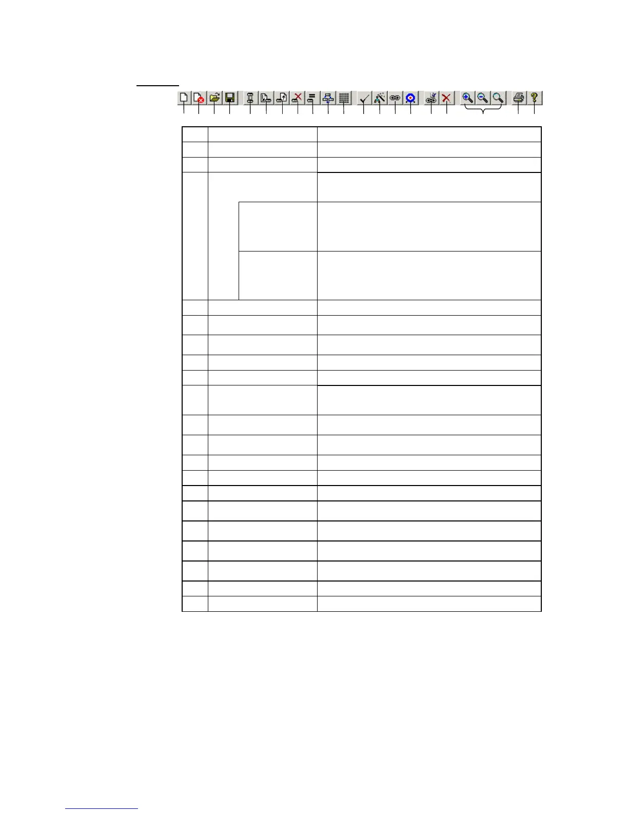
No. Icon Function
(1) New Creates new data link tables.
(2) Show All Network Nodes Shows all nodes in the network.
(3) Open Opens a data link tables, Files with any of the file name
extensions shown below can be opened.
When a file is opened, the proper editor starts up.
Controller Link .cl2 – CX-Net Controller Link/CLKSS data link tables
.cl3 – CX-Net Controller Link data link tables
.clk – CLKSS data link tables
.csv – CX-Net Controller Link data link tables
(tab-delineated text file)
SYSMAC LINK .sl3 – SYSMAC LINK data link tables
.slk – SYSMAC LINK data link tables for SYSMAC
Support Software
.csv – SYSMAC LINK data link tables (tab-delineated
text file)
(4) Save Saves the data link tables that are being edited.
(5) Toggle Network/Single
Node Operation
Specifies either all nodes or a single node for data
transfers.
(6) Transfer to PLC Downloads online data link tables from the computer to a
PLC.
(7) Transfer from PLC Uploads online data link tables to the computer.
(8) Delete Deletes data link tables.
(9) Verify Node Compares data link tables generated by CX-Integrator with
data link tables stored in the PLC. If they do not match, an
error dialog box is displayed.
(10) Data Link Operation/Status Displays the operation and data link status of manually set
data links.
(11) Automatic Data Link Setup Sets parameters for automatically set data links, and
transfers them to the startup node.
(12) Validate Table Checks data link tables.
(13) Wizard Executes the Datalink Wizard.
(14) Add Source Link Adds a node to the data links.
(15) Add Destination Adds the receive area of a participating node to the data
links.
(16) Set Source or Destination
Link Area Properties
Displays the Node Settings dialog box. This dialog box is
used to modify the node properties.
(17) Delete Link Destination
Service Area
Deletes nodes selected in the Data Link Configuration
Window, or deletes a receive area.
(18) Zoom In/Zoom Out/Zoom
Original
Zooms the Data Link Configuration Window in or out, or
returns it to the initial scale.
(19) Print Prints data link information.
(20) Help Displays help.
4-6
 Loading...


