4-3 Manually Setting Data Links
4-3-3 System Configuration Example
4-3-3 System Configuration Example
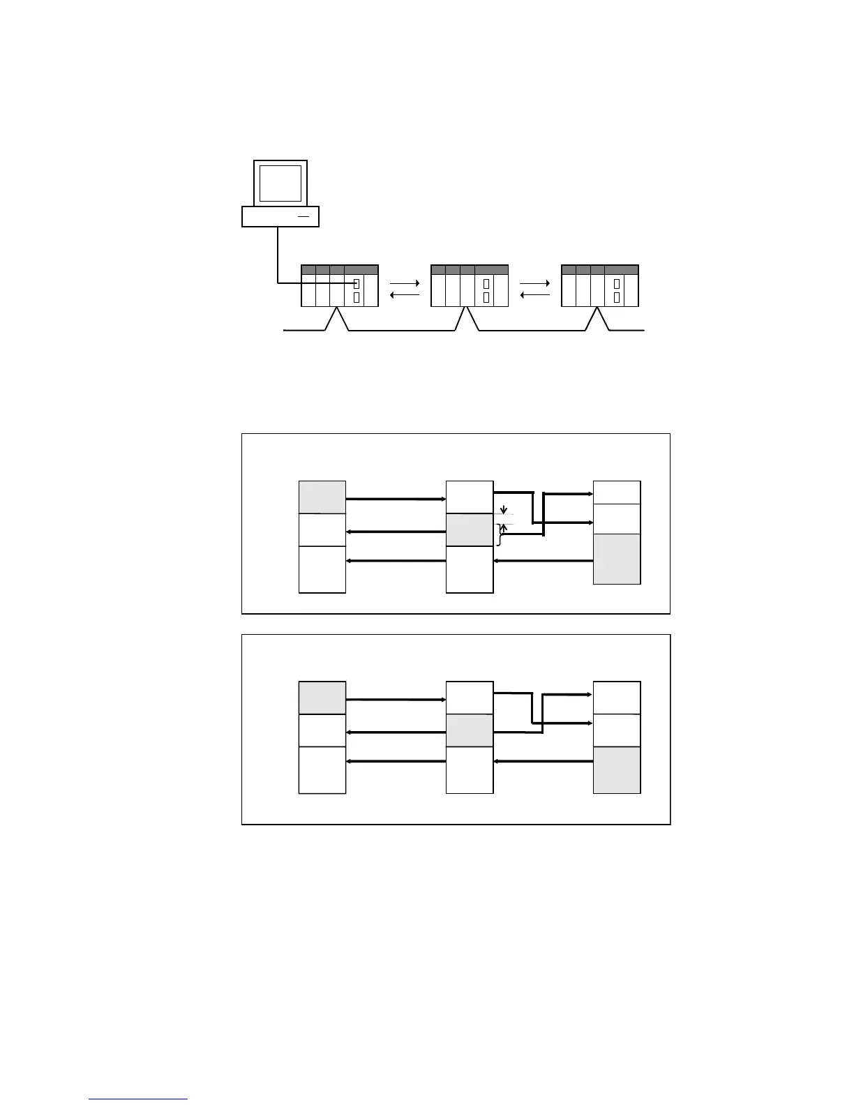
The procedure is described below, from data link creation through startup, taking a
Controller Link data link system as an example.
CX-Integrator
Controller Link networ
Receive
(#2)
Receive
(#3)
DM500
DM530
DM560
DM600
Node 1
Send
(#2)
Receive
(#1)
Receive
(#3)
Node 2
Send
(#3)
Receive
(#1)
Receive
(#2)
Node 3
DM600
DM630
DM660
DM700
DM730
DM760
Area 1
Send
(#1)
Receive
(#2)
Receive
(#3)
CIO 1000
CIO 1030
CIO 1060
CIO 1100
Node 1
CS1G
Send
(#2)
Receive
(#1)
Receive
(#3)
Node 2
CS1G
Send
(#3)
Receive
(#1)
Receive
(#2)
Node 3
C200HX
CIO 1200
CIO 1230
CIO 1300
IR 300
IR 320
IR 350
IR 390
CIO 1260
Size
20 words
Offset
10 words
DM700 DM800
The refresh sequence for nodes 1 and 2 is as follows: #1, #2, #3. For node 3, the
order is #2, #1, #3. Node address 03 does not receive all of the data sent from node
address 02. Rather, data from the 20 words (CIO 1240 to CIO 1259) beginning from
the start address +10 words (i.e., the offset) is received in IR 300 to IR 319. Other
data is received with no offset.
4-11
 Loading...


