4-4 Automatically Set Data Links
4-4-2 Controller Link Automatic Setup
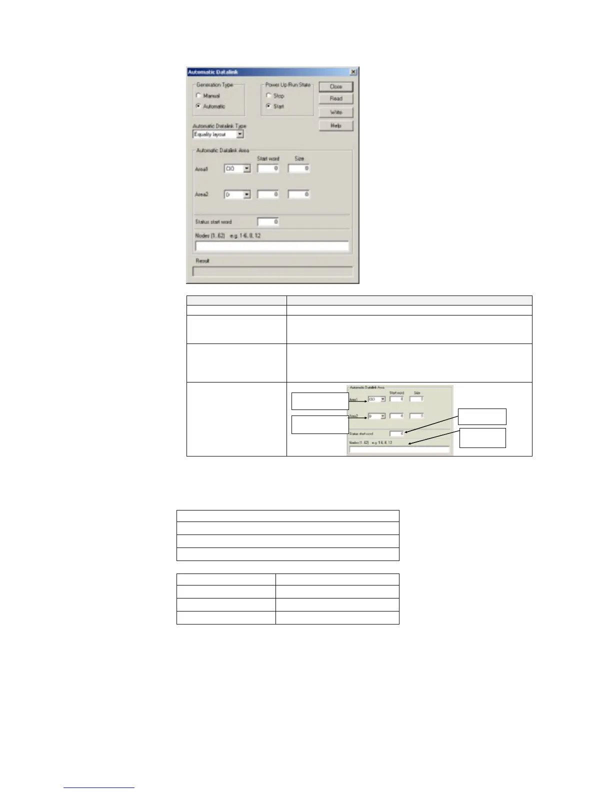
Set the following items.
Setting field Setting
Generation Type Select Automatic.
Automatic Datalink Type Select Equality layout, Common type, 1 to 1 type, or Chain type to
set the data link areas. Refer to Automatically Set Data Link Areas
for details.
Power Up Run State Select Start or Stop. Select Start to automatically start the data
links when power is turned ON without performing a specific
startup operation. If Start is set, it will be set in the Controller Link
startup node.
Automatic Data Link
Area
Set the status start word.
Set the nodes to
participate in the data
links.
Set the area, start word, and
size for area 2.
Set the area, start word, and
size for area 1.
Automatically Set Data Link Areas
If the following Controller Link Units/Support Boards are used, data links can be set
between a master and slaves using 1:N allocations. Any of the following four link
patterns can be used.
• Equality (same a previous automatic settings)
• Common type
• 1 to 1 type
• Chain type
Applicable Models:
• CS1W-CLK21-V1 • 3G8F7-CLK21-V1(-EV1)
• CS1W-CLK12-V1 • 3G8F7-CLK12-V1(-EV1)
• CS1W-CLK52-V1 • 3G8F7-CLK52-V1(-EV1)
• CJ1W-CLK21-V1
Note: Automatically set 1:N allocations are not possible for any models other than those
listed above. Refer to the Controller Link Unit Operation Manual for details.
4-43
 Loading...


