9-1 Controller Link Network Diagnostic Tool
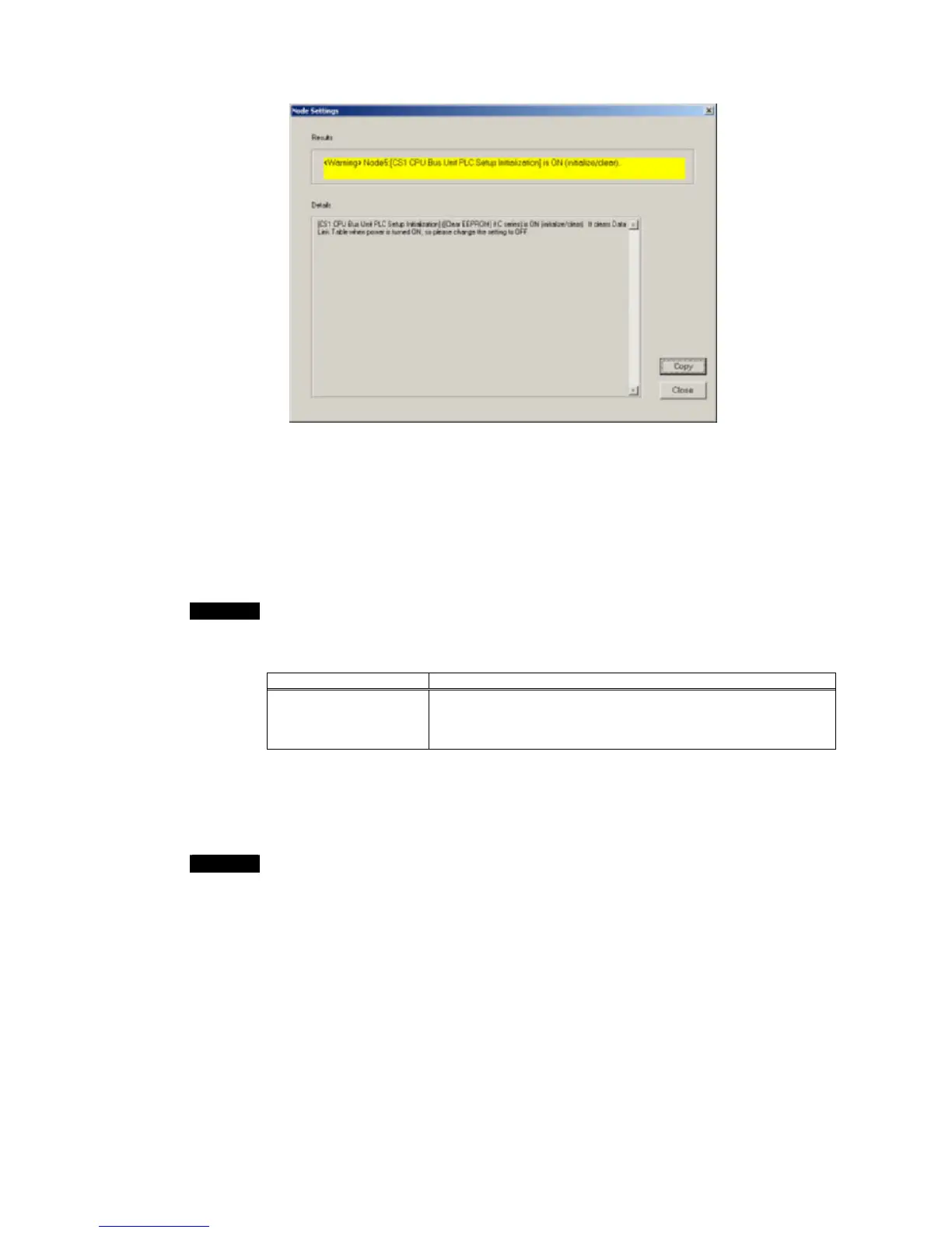
9-1-3 Diagnosing Node Settings
•
Check the details for all error and warning items in the results of diagnosis. Use the
Programming Devices, such as the CX-Programmer and Data Link Table Setting
Tool, to correct the settings.
•
Check all the information items to be sure that the settings are intentional. Use the
Programming Devices, such as the CX-Programmer and Data Link Table Setting
Tool, to correct any settings that are not suitable.
•
Select Diagnose – Node Settings from the Main Menu to diagnose the node
settings again.
Note
The status of the terminating resistance cannot be diagnosed for all nodes in networks
containing the following Controller Link Units/Boards. Visually confirm the settings for
these Units/Boards.
Item Units/Boards
Units for which the
terminating resistance
cannot be read
C200HW-CLK21Controller Link Unit (for C200HX/HG/HE PLCs)
CVM1-CLK21 Controller Link Unit (for CVM1/CV-series PLCs)
3G8F5-CLK21 ISA Bus Controller Link Support Board
CS1W-RPT01/02/03 Repeater Unit
• The Controller Link Network Diagnostic Tool cannot determine the order that nodes
are connected in Wired Networks. To enable diagnosis to see if the terminating
resistance is ON only at the ends the network, edit the node file so the nodes appear
in the actual order in which they are physically connected.
Note
•Any items not supported for a particular model will be grayed out on the display.
•If an item cannot be read from a node, the entire line for that node will be grayed out
on the display.
9-13
 Loading...


