9-1 Controller Link Network Diagnostic Tool
9-1-4 Diagnosing Disconnections
9-1-4 Diagnosing Disconnections
Disconnection Diagnosis
All nodes participating in the specified network are displayed in the order they are
physically connected. If the cable has been disconnected, the locations of
disconnections are displayed.
Disconnection diagnosis can be used only for Optical-ring Units/Boards in token ring
mode.
Diagnosis item Description
Order that nodes are
connected
Displays nodes in the order that nodes are connected. Connections between
node to communications ports SL and SL2 are displayed.
Network
disconnection status
The network is diagnosed to detect any disconnections. If there are any
disconnections, the locations of them are displayed.
Disconnection
Counter
Disconnection counters that measure each Controller Link Unit are
displayed.
Note
• Disconnection diagnosis will not be performed for a network that has not normally
reached ring status after starting the network.
•Disconnection diagnosis will not be performed for an Optical-ring Network in token
bus mode.
•Disconnections cannot be displayed for Wired Networks.
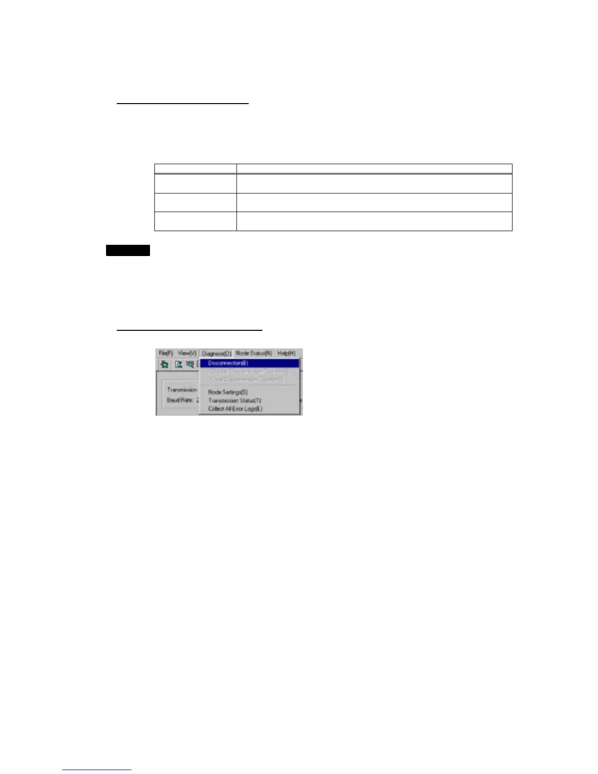
Diagnosing Disconnections
Select Diagnose – Disconnection from the Main Menu, or click the icon.
9-14
 Loading...


