9-1 Controller Link Network Diagnostic Tool
9-1-4 Diagnosing Disconnections
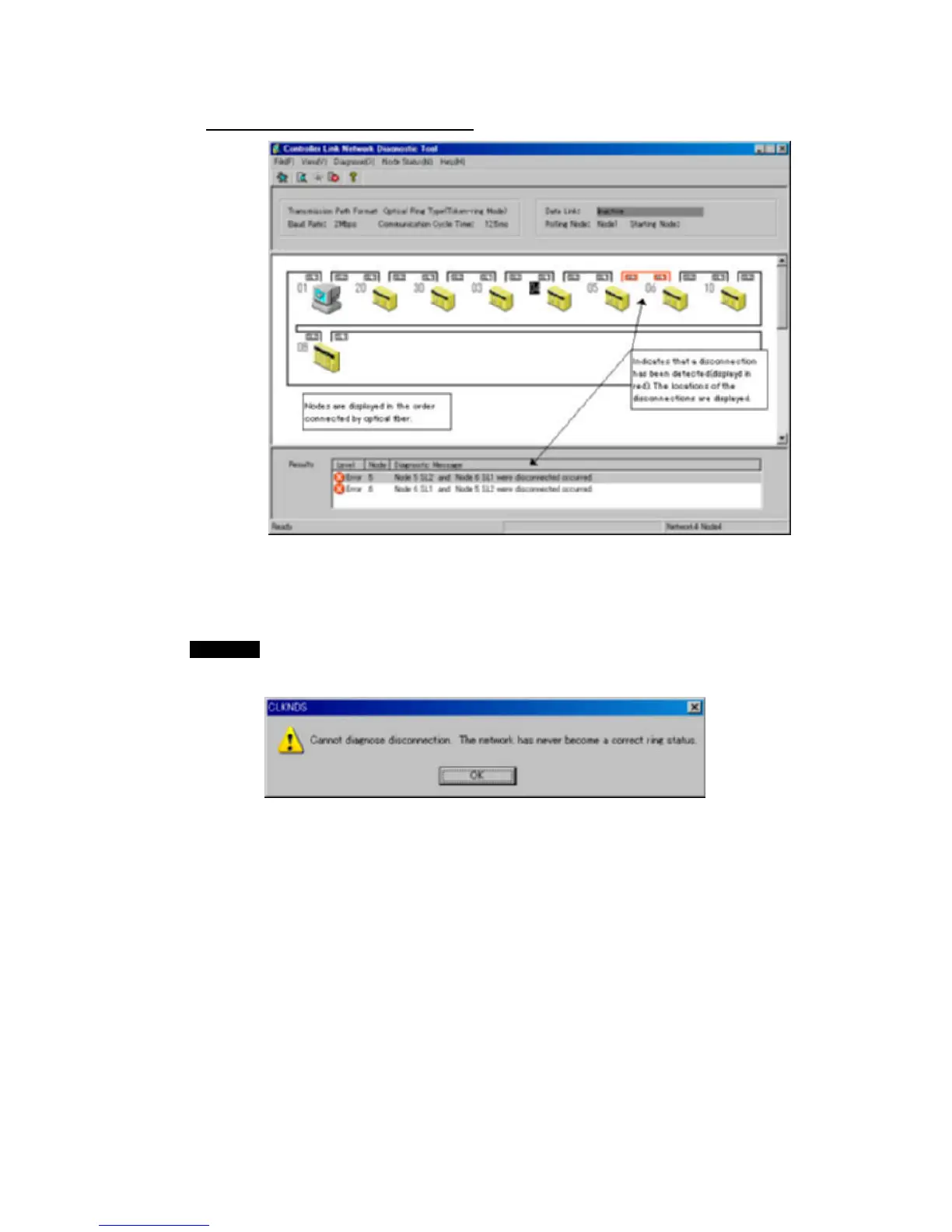
Disconnection Results Example
• Nodes are display in the order they are physically connected in the network.
•
The results of disconnection diagnosis are display in the results area.
Any disconnections that are detected are displayed in red.
•
Select Diagnose – Disconnection to display the disconnection diagnosis results
again.
Note
The node display for disconnection diagnosis does not display errors that have
occurred at the nodes (i.e., in Controller Link Units and CPU Units). If there are errors,
the following message box will be displayed.
Use the network status diagnosis to diagnose errors at the nodes (i.e., in Controller
Link Units and CPU Units).
9-15
 Loading...


