1-5 Window Descriptions
1-5-2 Main Window
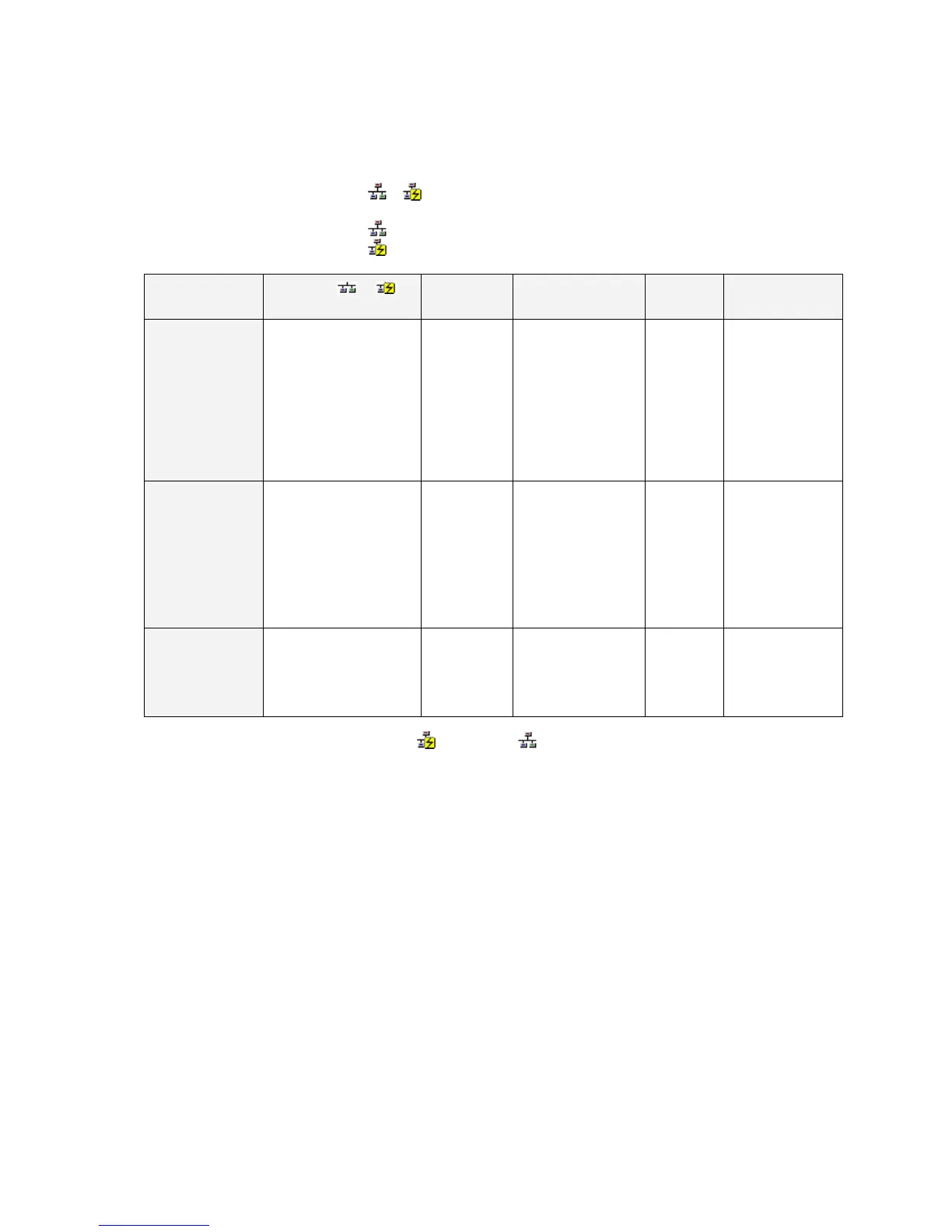
Communications Unit and Port Information for Target PLC
The following CPU Unit built-in serial ports, Inner Boards, and Communications Units
(referred to here as Communications Units/Ports) that are part of the target PLC are
displayed under TargetPLC in directory tree format.
Display format:
or
Unit name [Unit model] Net (network address) Node (node address) Unit (unit number or
FINS unit address)
: Not connected (access not possible).
: Connected (access possible).
Description:
Communications
Unit/port
Right of or :
Unit name
[Unit model]
Net (Network
address)
Node (Node
address)
Unit (Unit number
or FINS unit
address)
CPU Unit built-in
serial port
CPU Unit/port Target PLC’s
CPU Unit
model
The network address
(1 to 127, decimal),
when the serial port is
registered in the local
network table to treat
it as a network.
Note: “−” will be
displayed if the serial
port is not registered
in the local network
table.
− (Does not
change.)
Serial port’s FINS
unit address
(decimal)
Peripheral port: 253
RS-232C port: 252
Note: “−” will be
displayed if the
serial port is not
registered in the
local network table.
Serial port on
Inner Board
(Nothing
displayed if an
Inner Board is not
mounted.)
Serial Communications
Board
Serial Com-
munications
Board model
Same as above. − (Does not
change.)
Serial port’s FINS
unit address
(decimal)
Port 1: 225
Port 2: 226
Note: “−” will be
displayed if the
serial port is not
registered in the
local network table.
Communications
Unit name, Model
Communications Unit
name (Ethernet Unit,
Controller Link Unit,
SYSMAC LINK Unit, or
DeviceNet Unit)
Communica-
tions Unit
model
Network address (1 to
127, decimal)
Note: “−” will be
displayed if a local
network table is not
registered.
Node
address
(node ID on
the network)
Unit number
(decimal)
(Rotary switch on
front of CPU Bus
Unit: 0 to 15)
If a connection is established and access is enabled for a Communications Unit/port, the
icon on the left will be
instead of .
Right-click the Communications Unit/port and select Connect to connect to the
Communications Unit/port and enable access. (With the CX-Integrator, only one
Communications Unit/port can be accessed at any one time.)
The actual network configuration can then be uploaded by right-clicking the Communications
Unit/port and selecting Transfer
−
Network to PC.
1-24
 Loading...


