2-3 Uploading Network Configurations and Checking for Communications
Unit Errors
2-3-3 Checking and Correcting Communications Unit Errors
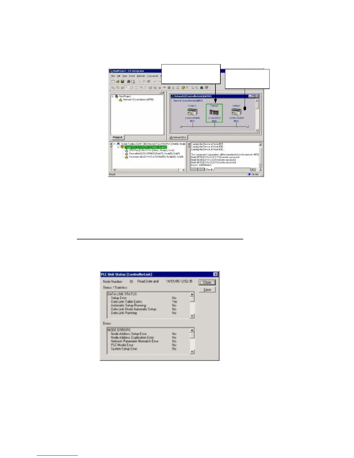
4. The network configuration uploaded from the Unit will be displayed in the Network
Configuration Window.
The target PLC is displayed
with a green border.
The window
background will be
gray when online.
5. Check the connection status of the nodes. To check the CPU Unit and
Communications Units for errors, right-click the node in the Network Configuration
Window and select Error Log or Status/Error of Communication Unit from the
pop-up menu.
2-3-3 Checking and Correcting Communications Unit Errors
Checking a Communications Unit’s Status and Errors
Right-click the target PLC in the Network Configuration Window and select
Status/Error of Communication Unit from the pop-up menu.
The PLC Unit Status Dialog Box will be displayed. In this example, a Controller Link
Unit is selected.
Note: The Communications Unit’s status and error information can be saved as a CSV file by
clicking the Save Button, so the Communications Unit’s status at that point can be read
from the CSV file later and analyzed.
2-25
 Loading...


