Item
FH series:
FH-1000/2000/3000/5000 series
Communi-
cations
EtherCAT
• The Communications Module is set for each line.
• The communications settings can be set only for line 0.
The settings are applied as shown below.
Output control: The same setting is used for all lines.
Output period: The same setting is used for all lines.
Output setting: This is set for each line.
• The I/O ports (areas) for communications between the FH series Sensor Con-
troller and master are assigned as shown below.
I/O ports for the Command Area: I/O ports are assigned for each line.
I/O ports for the Response Area: I/O ports are assigned for each line.
I/O ports for the Output Area: I/O ports are assigned for each line.
The I/O ports in the Sysmac Error Status Area are shared by all lines.
• The maximum data size that can be output depends on the number of lines,
as shown in the following table.
1 to 5 lines: 256 bytes max.
6 to 8 lines: 128 bytes max.
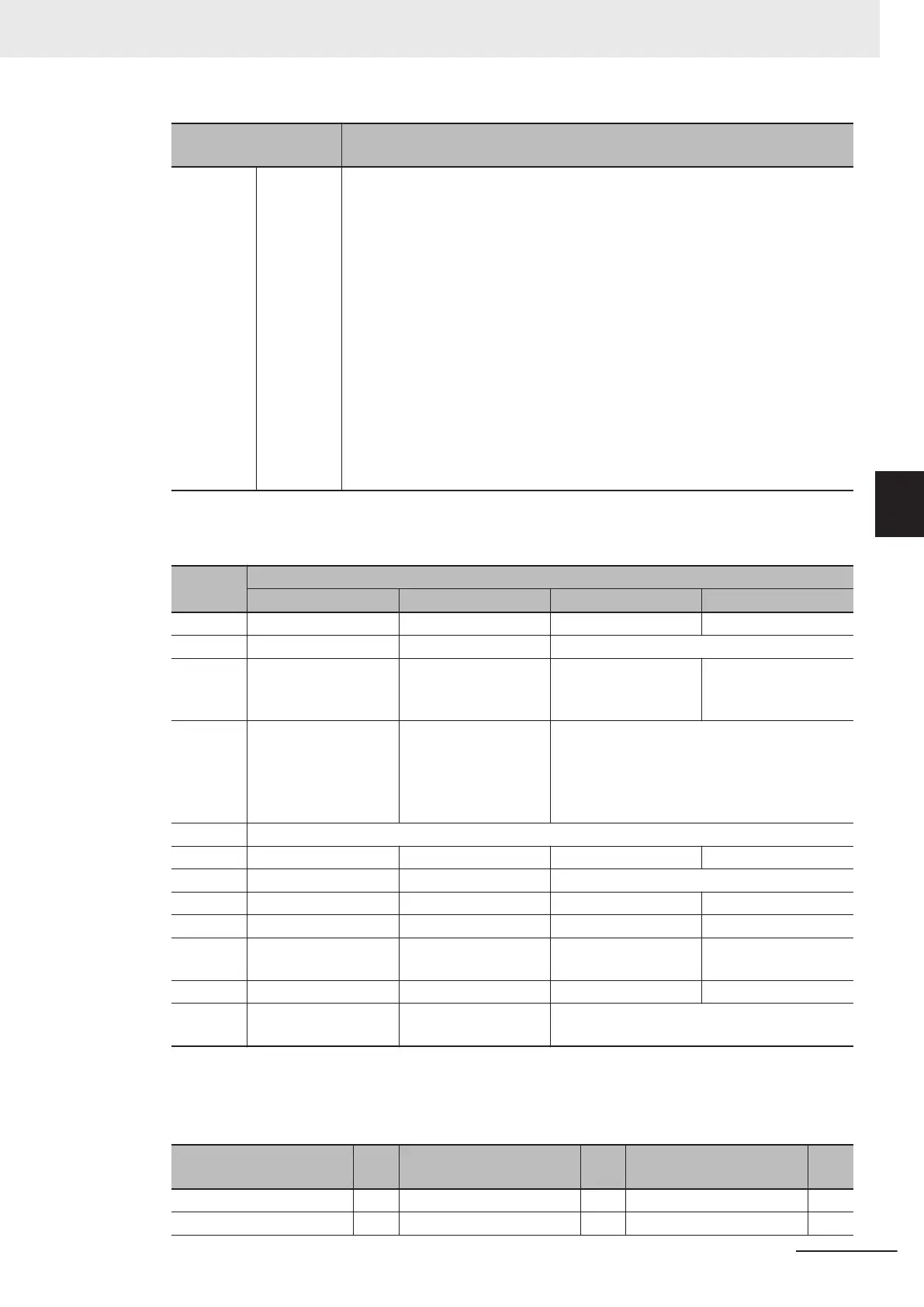
• Table: Parallel I/O Functions and Parallel Terminals for Multi-line Randomtrigger Mode
FH-1000/FH-2000/FH-3000/FH-5000 series
I/O
Number of lines
1 line 2 lines 3 to 4 lines 5 to 8 lines
STEP STEP0 STEP0 or STEP1 STEP0 to STEP3 STEP0 to STEP7
DSA DSA0 DSA0 or DSA1 No output
DI DI0 to DI7 DILINE0, DI0 to DI7
(shared by all lines)
DILINE0 to DILINE1,
DI0 to DI7 (shared by
all lines)
DILINE0 to DILINE2,
DI0 to DI7 (shared by
all lines)
ENC
(phases
A, B, and
Z)
ENC0 phase A, ENC0
phase B, and ENC0
phase Z
ENC0 phase A, ENC1
phase A, ENC0 phase
B, ENC1 phase B,
ENC0 phase Z, and
ENC1 phase Z
No output
ACK ACK (shared by all lines)
RUN RUN0 RUN0 or RUN1 RUN0 to RUN3 No output
GATE GATE0 GATE0 or GATE1 No output
BUSY BUSY0 BUSY0 or BUSY1 BUSY0 to BUSY3 BUSY0 to BUSY7
OR OR0 OR0 or OR1 OR0 to OR3 OR0 to OR7
ERROR ERROR0 ERROR0 or ERROR1 ERROR0 to ERROR3 ERROR (shared by all
lines)
READY READY0 READY0 or READY1 READY0 to READY3 READY0 to READY7
DO DO0 to DO15 Line 0: D00 to D07
Line 1: D8 to D15
No output
The following processing items are supported in the multi-line random trigger mode:
OK:Supported processing item, RST: Processing item with restricted support,
-:Unsupported processing item
Processing item
Sup-
port
Processing item
Sup-
port
Processing item
Sup-
port
Camera Image Input OK Extract Color Filter OK Conditional Branch OK
Camera Image Input FH OK Anti-Color Shading OK End OK
4 Setting the Controller
4 - 21
FH/FHV Series Vision System User’s Manual (Z365-E1)
4-4 Setting Operation Mode [Startup Settings]
4
4-4-1 Setting the Operation Mode
 Loading...


