Precautions for Correct Use
The settings of the Multi-line Random-trigger Mode Settings apply only to the FH series Sen-
sor Controller.
l
Functional Limitations of Multi-line Random-trigger Mode
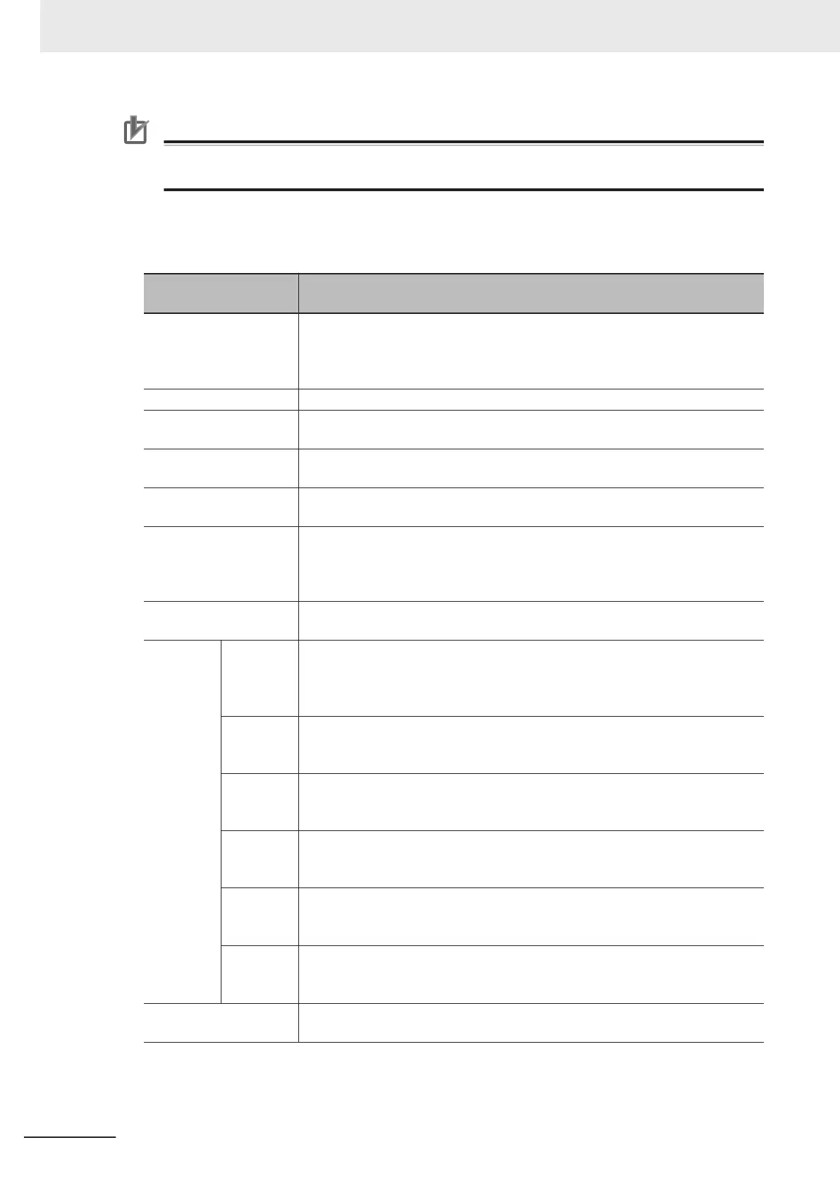
Keep the following points in mind when using Multi-line Random-trigger Mode.
Item
FH series:
FH-1000/2000/3000/5000 series
Processing time
• If the processing load for multiple lines is high, there may be fluctuation in
measurement times.
• If data logging for multiple lines is to the same drive, measurement times may
become longer.
Number of Cameras The maximum number of Cameras is 8 for all lines.
Error messages Error messages are the same for lines 0 to 7. If an error occurs on any of the
lines, an error message is displayed and the ERROR signal is turned ON.
Saving data in the Con-
troller
To save data in the Controller, the data must be saved separately for each line.
Save folder for captured
images
When you click Capture on the Measurement Manager Bar, captured images are
always saved to the folder that is specified for line 0.
Date-time setting, lan-
guage setting, operation
mode setting and Net-
work drive setting.
These settings can be set only for line 0.
View Images can be displayed simultaneously for all lines. Use layout modification to
set the display position and size for the Main Window for each line.
Communi-
cations
Parallel
• Parallel communications can be set only for line 0. The settings for line 0 are
applied to lines 1 to 7.
• Refer to Table 1 for details on the differences between parallel I/O and parallel
terminals.
Normal
(RS- 232C/
422)
RS-232C can be set only for line 0.
Lines 1 to 7 cannot be used.
Normal
(Ethernet)
• To use Ethernet, use a different port number for each line.
• The IP address for the Controller cannot be set for lines 1 to 7 (the IP address
for line 0 is used).
PLC Link
(RS-232C/
422)
RS-232C can be set only for line 0.
Lines 1 to 7 cannot be used.
PLC Link
(Ethernet)
• To use Ethernet, use a different port number for each line.
• The IP address for the Controller cannot be set for lines 1 to 7 (the IP address
for line 0 is used).
EtherNet/I
P
• To use EtherNet/IP, use an EDS file that matches the line to be used.
• Specify different I/O memory addresses for the sending area and receiving
area for line 0 and for lines 1 to 7.
STEP setting The value of the STEP signal filter for the most recently set line is applied to all
lines.
4 Setting the Controller
4 - 20
FH/FHV Series Vision System User’s Manual (Z365-E1)
 Loading...


