2 Drag the following processing items from under Inspection and measurement support
items, or click the Insert button.
• Parallelize
• Parallelize Task
3
Program the processing items to execute in parallel between two Parallelize Task processing
items.
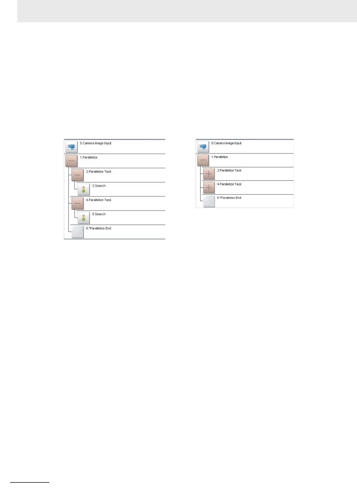
Example:
Fully Expanded Paralle Blocks Collapsed
The Parallelize processing item is the parent, and everything up to the Parallelize End processing
item is a child.
Additionally, the Parallelize Task processing item is the parent, and everything up to the step just
before the next Parallelize Task processing item or the Parallelize End processing item is a child.
There is no settings dialog box for Parallelize processing items.
The Parallelize End processing item is not displayed in the list of items. (It is registered as a set
with the Parallelize processing item).
l
Precautions on Flow Editing
• Editing operations on parallel blocks and task blocks, such as register, move, delete, copy, and
paste, and unit save and load operations, are performed on the parallel block as a group.
• You cannot delete a Parallelize End processing item by itself. It is deleted as a set with the
Parallelize processing item.
• You cannot paste or move items within the same parallel block.
• If a processing item in a parallel block is set to reference data in a processing unit that is inside
the block, and if that block is copied, the reference will be replaced with a reference to the unit in
the block at the copy destination.
References to a unit that is outside the parallel block will be retained.
• You cannot move, paste, or load a task block outside of its parallel block.
• When parallelizing processing units using variables, the processing units are not subject to auto-
matic parallelization. Therefore, rearrange the parallelization flow using parallelization processing
items. When rearrange the flow, consider the execution timing of the processing unit and the var-
iable input/output.
4 Setting the Controller
4 - 34
FH/FHV Series Vision System User’s Manual (Z365-E1)
 Loading...


