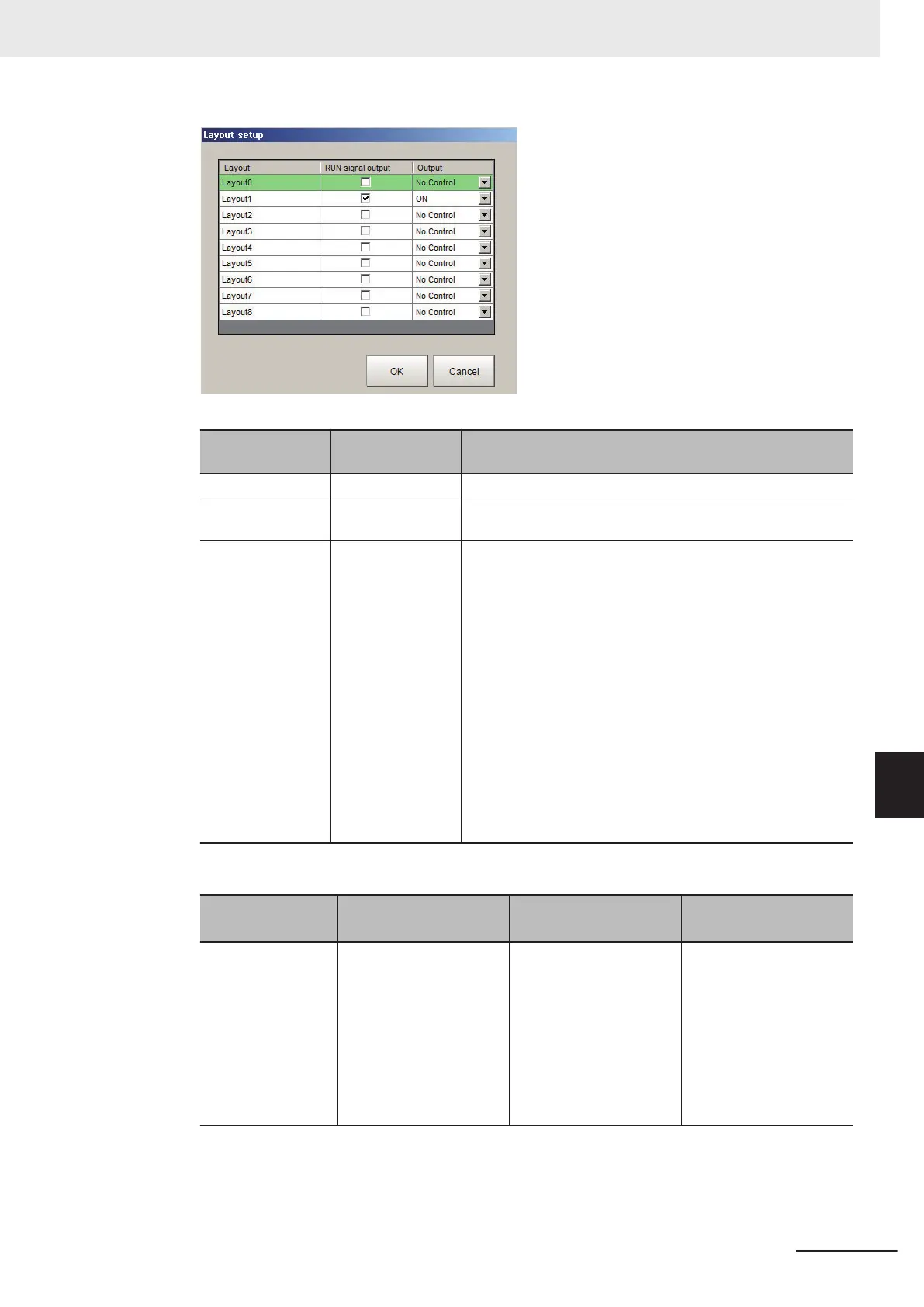
Item
Setting value
[Factory default]
Description
Layout 0 to 32 characters Layout name
RUN signal out
• Checked
• [Unchecked]
The RUN signal is turned on when the box is checked.
Output
• [Not control]
• ON
• OFF
Sets whether or not to output the execution results of the Re-
sult output processing units.
• Not control:
The state of the outputs that were in effect before the lay-
out was changed is retained. If Output is selected just be-
fore the layout is changed, the outputs stay ON, and if
Output is not selected, the outputs stay OFF.
• ON:
Data is output when a Results output processing unit is
executed in the measurement flow during execution of a
measurement.
• OFF:
Data is not output even when a Results output processing
unit is executed in the measurement flow for a measure-
ment.
The operation of the output signals in each state is as follows. Set it as necessary.
State
Layout 0, 2 to 7 dis-
played
*1
Just after switching
scenes /layouts
At startup
Output condition for
output signal
Follow the Output setting
in the measurement win-
dow.
Follow Output on
Layout setup dialog.
Follow the setting of
Startup layout of Basic
on System Settings in
Tool menu.
For the selected layout in
the Layout setup dialog,
the output is not per-
formed when the Output
setting is No Control.
*1. In the default setting, the check box of the Output for layout 1 and 8 is not displayed.
8 Setting Windows
8 - 23
FH/FHV Series Vision System User’s Manual (Z365-E1)
8-3 Arranging Windows [Layout Functions]
8
8-3-2 Setting the Behavior of Output Signals for Each Layout [Layout
setup]
 Loading...


