Operation mode Setting
Standard Line No. = 0
Double Speed Multi-input Line No. = 0
Non-stop adjustment Measurement window Line No. = 0
Non-stop adjustment window Line No. = 1
Multi-line random trigger
*1
Line 0 side Line No. = 0
Line 1 side Line No. = 1
Line 2 side Line No. = 2
Line 3 side Line No. = 3
Line 4 side Line No. = 4
Line 5 side Line No. = 5
Line 6 side Line No. = 6
Line 7 side Line No. = 7
*1. The FH series Sensor Controller is capable to have up to eight lines. Set the line number based on
the number of lines set in the Sensor Controller.
If a Line No. other than the above was selected, the remote operation cannot be connected to
Sensor Controllers.
6
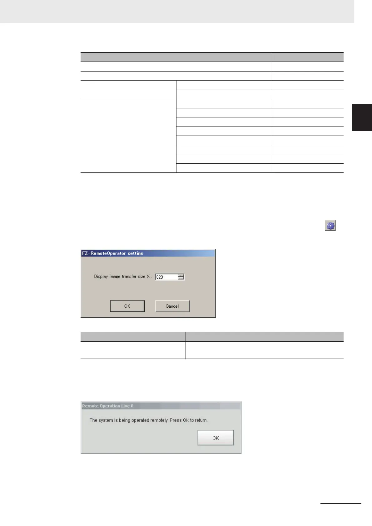
Change the size of an image to transfer with the remote operation as necessary. Select ( )
to set.
Item Description
Display image transfer size (Size of the
image to transfer)
Sets the width of the image displayed in the remote operation
window. (default: 320)
7 Click Start.
In the FH series, A Remote operation message is displayed on the sensor controller when re-
mote operation is established. In the above state, you can not operate the Sensor Controller.
10 Advanced Usage
10 - 11
FH/FHV Series Vision System User’s Manual (Z365-E1)
10-1 Remotely Operating the
Controller [Remote Operation]
10
10-1-2 Connection Method for Remote Operation
 Loading...


