Controlling Operation and Outputting Data with the Sensor's Standard Parallel Connection
238
FQ2 User’s Manual
Wiring
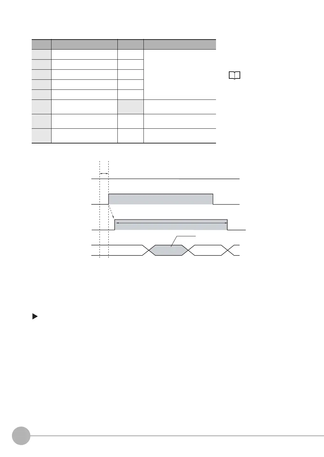
Timing Chart
1. Turn ON IN5 while IN0 to IN4 are OFF. If status is held while the BUSY signal is OFF, continuous
measurements will begin and the BUSY signal will remain ON while continuous measurements are being
performed.
2. Continuous measurements end when IN5 is turned OFF.
Settings
[In/Out] − [I/O setting] − [I/O terminals] − [Input] − [Input mode]
Press [Expanded mode].
Color Signal State Description
The signals shown at the left
are used.
Refer to the following informa-
tion for signal wiring.
Wiring: p. 42
Gray IN0 OFF Command parameters for continu-
ous measurements
Green IN1 OFF
Red IN2 OFF
White IN3 OFF
Purple IN4 OFF
Ye l l o w I N 5 ON Command input for continuous
measurements
Black OUT0 (OR) -- Overall judgement (default assign-
ment)
Orange OUT1 (BUSY) -- Processing in progress (default
assignment)
OFF
ON
OFF
ON
OFF
ON
OR signal
Turned ON when overall judgement is NG.
(OR output: ON for NG)
ON while measurements are
being processed (depends on
BUSY output conditions)
BUSY signal
Start continuous measurements
End continuous measurements
IN5 signal
IN0 to IN4 signals
are OFF
Allow 5 ms min. and then turn ON IN5.