Controlling Operation and Outputting Data with the Sensor's Standard Parallel Connection
FQ2 User’s Manual
239
8
Controlling Operation and Outputting Data
with a Parallel Connection
Sample Ladder Program
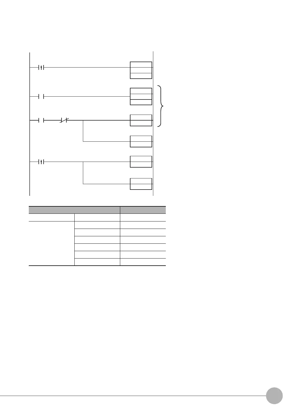
The following sample program is used to input a IN5 signal to perform continuous measurements. Continuous
measurements will be started when W0.00 turns ON and stopped when W0.01 turns ON.
• I/O Signal Allocations
Signal Address
Output signals OUT1 (BUSY signal) CIO 0.01
Input signals IN0 CIO 1.08
IN1 CIO 1.09
IN2 CIO 1.10
IN3 CIO 1.11
IN4 CIO 1.12
IN5 CIO 1.15
MOV
#0000
Q:1
W0.00
0000
#5
TMHH
SET
IN5
T0000
OUT1
W0.00
RSET
W0.00
RSET
IN5
W0.01
RSET
W0.00
Continuous
measurement
command bit
Continuous
measurement
command bit
BUSY signal
Continuous
measurement
stop bit
When the continuous measurement command
bit (W0.00) turns ON, the command
parameter for continuous measurements
(00000) is output to Q:1 (IN0 to IN4).
If the BUSY signal is OFF 5 ms after the
command parameter is output, the command
input for continuous measurements (IN5) is
turned ON and continuous measurements start
When the continuous measurement stop bit
(W0.01) turns ON, the command input for
continuous measurements (IN5) is turned
OFF and continuous measurements stop.