Controlling Operation and Outputting Data with the Sensor's Standard Parallel Connection
FQ2 User’s Manual
251
8
Controlling Operation and Outputting Data
with a Parallel Connection
Turning the ERROR Signal OFF
The ERROR signal turns ON when an error occurs.
After removing the cause of the error, turn the ERROR signal OFF using one of the following methods.
Method 1: Input an error clear command from an external device such as a PLC.
Method 2: Input a measurement trigger again.
(For example, turn the TRIG signal ON during a one-shot measurement.)
The ERROR signal will turn OFF when measurement is executed correctly.
Settings
[In/Out] − [I/O setting] − [I/O setting] − [Input] − [Input mode]
Press [Expand mode].
Wiring
Timing Chart
This function can be used in Run Mode only.
Color Signal State Description
The signals shown at the left
are used.
Refer to the following
information for signal wiring.
2-4 Wiring: p. 42
Gray IN0 OFF Command parameter for clearing errors
Green IN1 OFF
Red IN2 ON
White IN3 OFF
Purple IN4 OFF
Ye l l o w I N 5 ON Command input for clearing errors
Orange OUT1 (BUSY) -- Processing in progress (default)
Light blue OUT2 (ERROR) -- ERROR signal (default)
1 Turn OFF IN0 to IN1 and IN3 to IN4
and turn ON IN2.
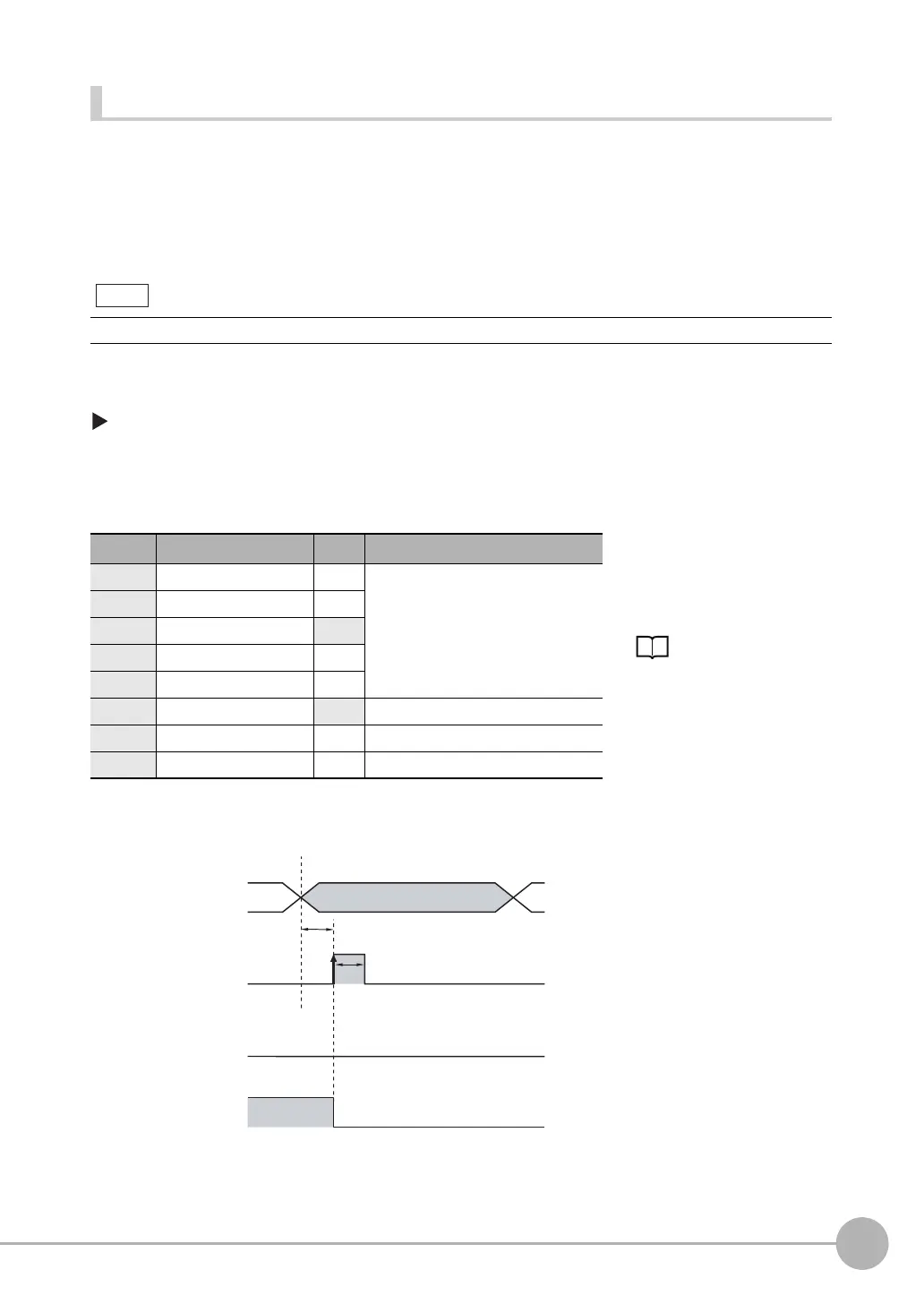
2 Turn ON the IN5 signal while the
BUSY signal is OFF to clear the error.
Note
OFF
ON
OFF
ON
OFF
ON
ERROR signal
BUSY signal
IN5 signal ON for 1 ms min.
Allow 5 ms min. and then
turn ON IN5.
IN0 to IN4 signals