Controlling Operation and Outputting Data with the Sensor's Standard Parallel Connection
FQ2 User’s Manual
253
8
Controlling Operation and Outputting Data
with a Parallel Connection
Save Data in Sensor
You can save the current settings (scene data and system data) in the Sensor.
Settings
[In/Out] − [I/O setting] − [I/O setting] − [Input] − [Input mode]
Press [Expand mode].
Wiring
Timing Chart
This function can be used in Run Mode only.
Color Signal State Description
The signals shown at the left
are used.
Refer to the following
information for signal wiring.
2-4 Wiring: p. 42
Gray IN0 ON Command parameters for saving data to
the Sensor
Green IN1 OFF
Red IN2 OFF
White IN3 OFF
Purple IN4 OFF
Ye l l o w I N 5 ON Command input for saving data to the
Sensor
Orange OUT1 (BUSY) -- Processing in progress (default)
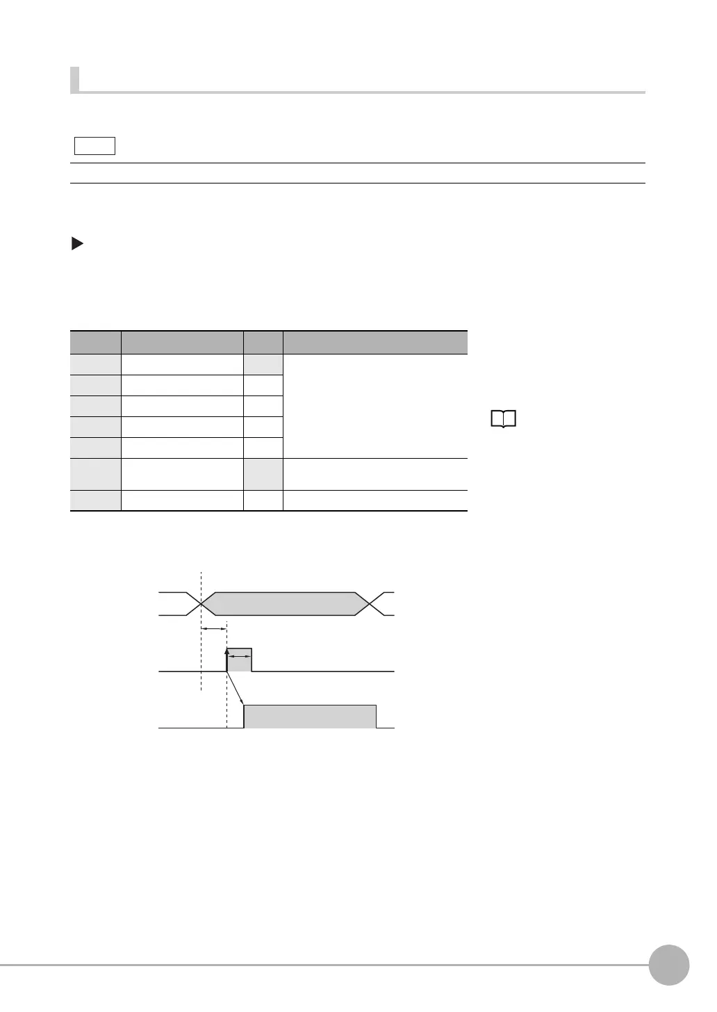
1 Turn ON IN0 and turn OFF IN1 to IN4.
2 Turn ON the IN5 signal while the
BUSY signal is OFF to save the data
in the Sensor.
Note
OFF
ON
Saving data
in Sensor started.
Saving data in
Sensor completed.
OFF
ON
BUSY
signal
IN5 signal
ON for 1 ms min.
Allow 5 ms min. and then
turn ON IN5.
IN0 to IN4
signals