PLC Link Connections
336
FQ2 User’s Manual
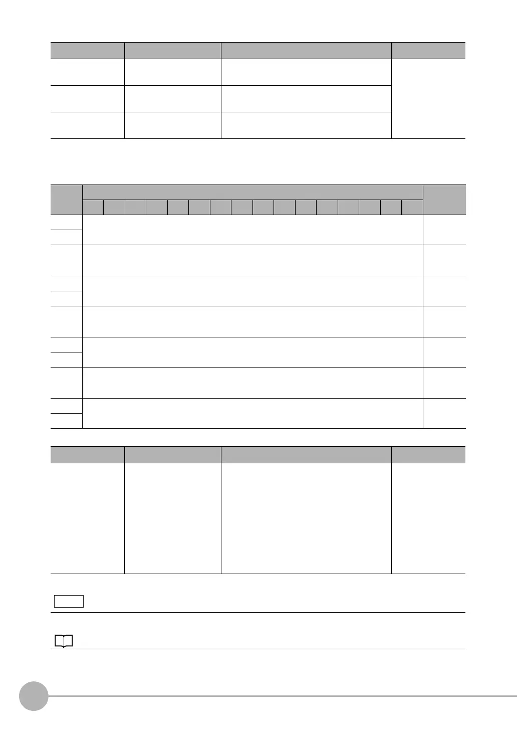
● Output Area
Vision Sensor (Slave) to PLC (Master)
Command code Command code This I/O port returns the command code that
was executed.
Command/
response commu-
nications
Response code Response code This I/O port contains the response code of the
executed command.
Response data Response data This I/O port contains the response data of the
executed command.
First
word
Bits Contents
15 14 13 12 11 10 9 8 7 6 5 4 3 2 1 0
+0
DATA 0
Output data
0 (32 bits)
+1
·
·
·
·
·
·
·
·
·
+14
DATA 7
Output data
7 (32 bits)
+15
·
·
·
·
·
·
·
·
·
+128
DATA 63
Output data
63 (32 bits)
+129
·
·
·
·
·
·
·
·
·
+512
DATA 255
Output data
255 (32 bits)
+513
Signal Signal name Function Application
DATA0-255 Output data 0 to 255 These I/O ports output the output data that is
specified for the data output method.
The range of the data that can be output is
determined by the set value of the [Max output
data] (number of output data upper value)
parameter setting as follows:
Minimum setting (32 bytes): Output data 0 to 7
Default setting (256 bytes): Output data 0 to 63
Maximum setting (1,024 bytes): Output data 0
to 255
Data output after
measurements
If the size of data that is output exceeds the set value of the number of output data upper value setting, the remain-
ing data will be discarded.
Allocating Output Data p. 332
Signal Signal name Function Application