PLC Link Connections
FQ2 User’s Manual
337
Connecting through Ethernet
9
Command Tables for PLC Link Communications
This section describes the commands used in PLC Link communications.
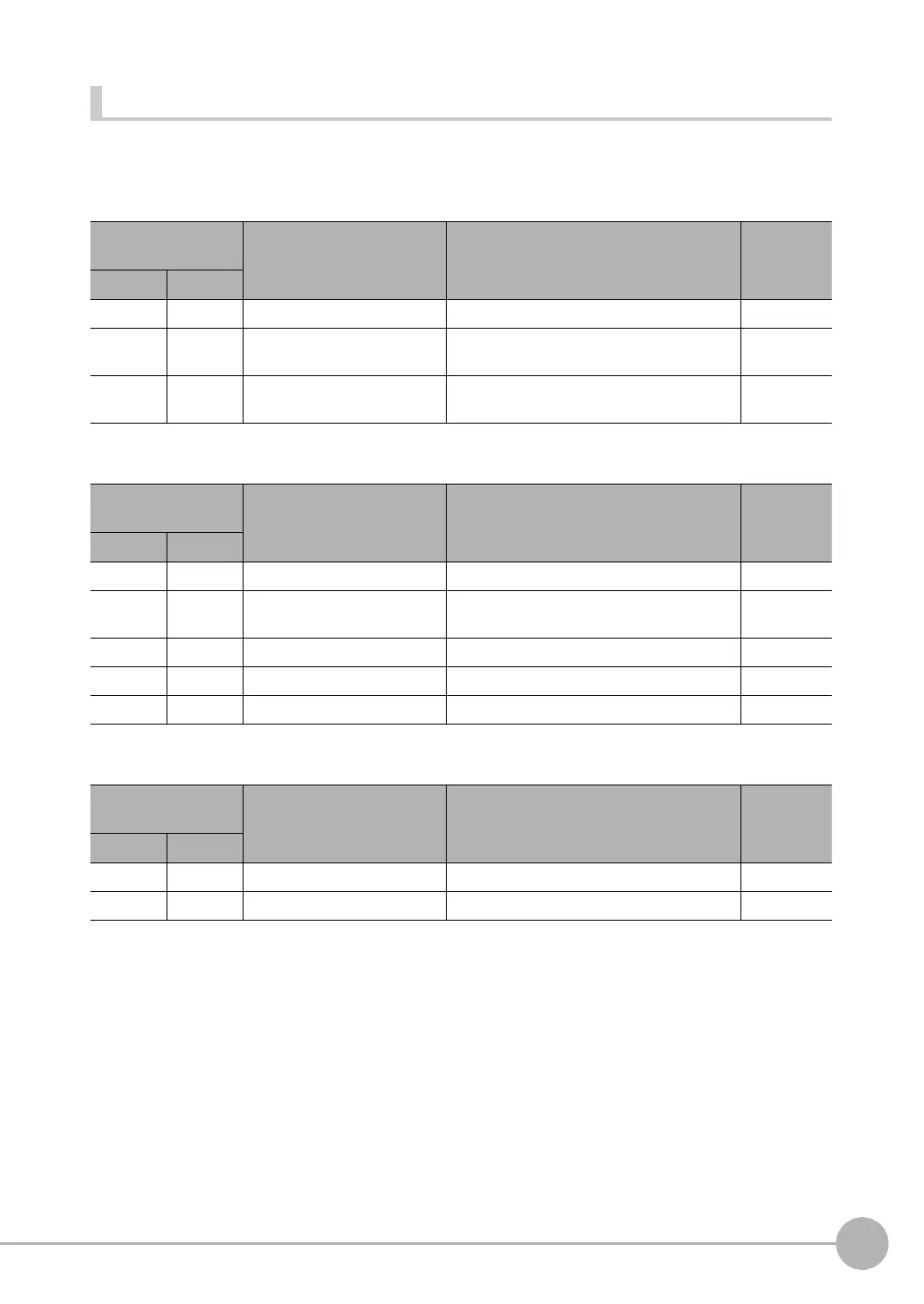
● Measurement Control Commands
● Utility Commands
● Scene Control Commands
First word of com-
mand area (hex)
Command name Function Reference
+2 +3
1010 0010 Single Measurement Performs a single measurement. p. 338
1020 0010 Start Continuous Measure-
ments
Executes continuous measurements. p. 339
1030 0010 End Continuous Measure-
ments
Ends continuous measurements. p. 339
First word of com-
mand area (hex)
Command name Function Reference
+2 +3
2010 0010 Clear Measurement Values Clears all measurement result values. p. 340
3010 0010 Save Data in Sensor Saves the current system data and scene
groups in the Sensor.
p. 340
4010 0010 Re-register Model Registers the model again. p. 340
4020 0010 External Teaching Performs reteaching. p. 341
F010 0010 Reset Vision Sensor Resets the Vision Sensor. p. 341
First word of com-
mand area (hex)
Command name Function Reference
+2 +3
1000 0020 Get Scene Number Acquires the current scene number. p. 342
1000 0030 Select Scene Changes to the specified scene number. p. 342