Menu Tables
406
FQ2 User’s Manual
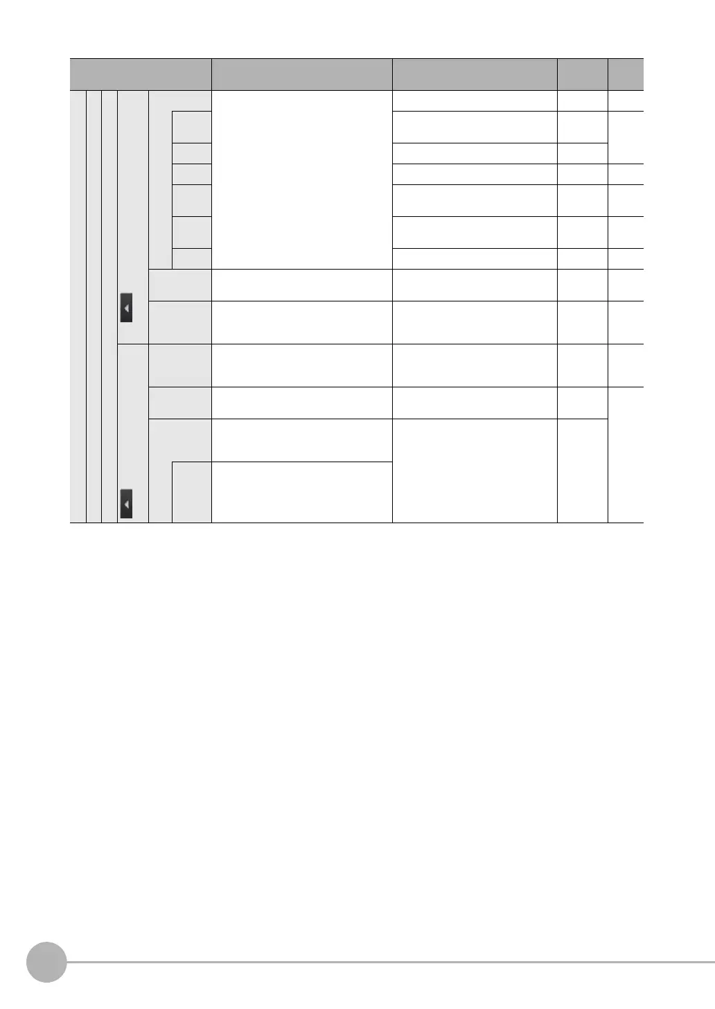
Image adjustment (Position compensation items)
Basic
Teac h
for Search Position Compensation and Shape
Search Position Compensation
Model region Used to specify the region of the image
to register as the model with a combina-
tion of figures.
--- Scene ---
Add Rectangle, Ellipse, Wide circle, or
Polygon
Scene ---
Delete --- Scene
Copy --- Scene ---
Con-
sole
--- Scene ---
OR/
NOT
OR (default) or NOT Scene ---
One/All One or All Scene ---
Insp. region Adjusts the size and position of the mea-
surement region.
--- Scene ---
Detection
point
You can specify which part of the model
to detect as coordinates during inspec-
tions
--- Scene ---
for Edge Position Compensation
Insp. region Adjusts the size and position of the mea-
surement region, changes the measure-
ment direction, etc.
--- Scene ---
Color ON/
OFF
Sets whether to specify an edge color. ON or OFF (default) Scene ---
Set color. Specifies the color of the image for edge
detection (i.e., the border between the
measurement object and background).
R: 0 to 255
B: 0 to 255
G: 0 to 255
Scene
Color
palette
Displays a palette for color specification.
Menu command Description Setting range Data Refer-
ence
 Loading...


