Wiring
FQ2 User’s Manual
2
Installation and Connections
47
FQ-SDU20/SDU25 Parallel Pin Signal Names
*1: Leave all signal terminals that are labeled “NC” open.
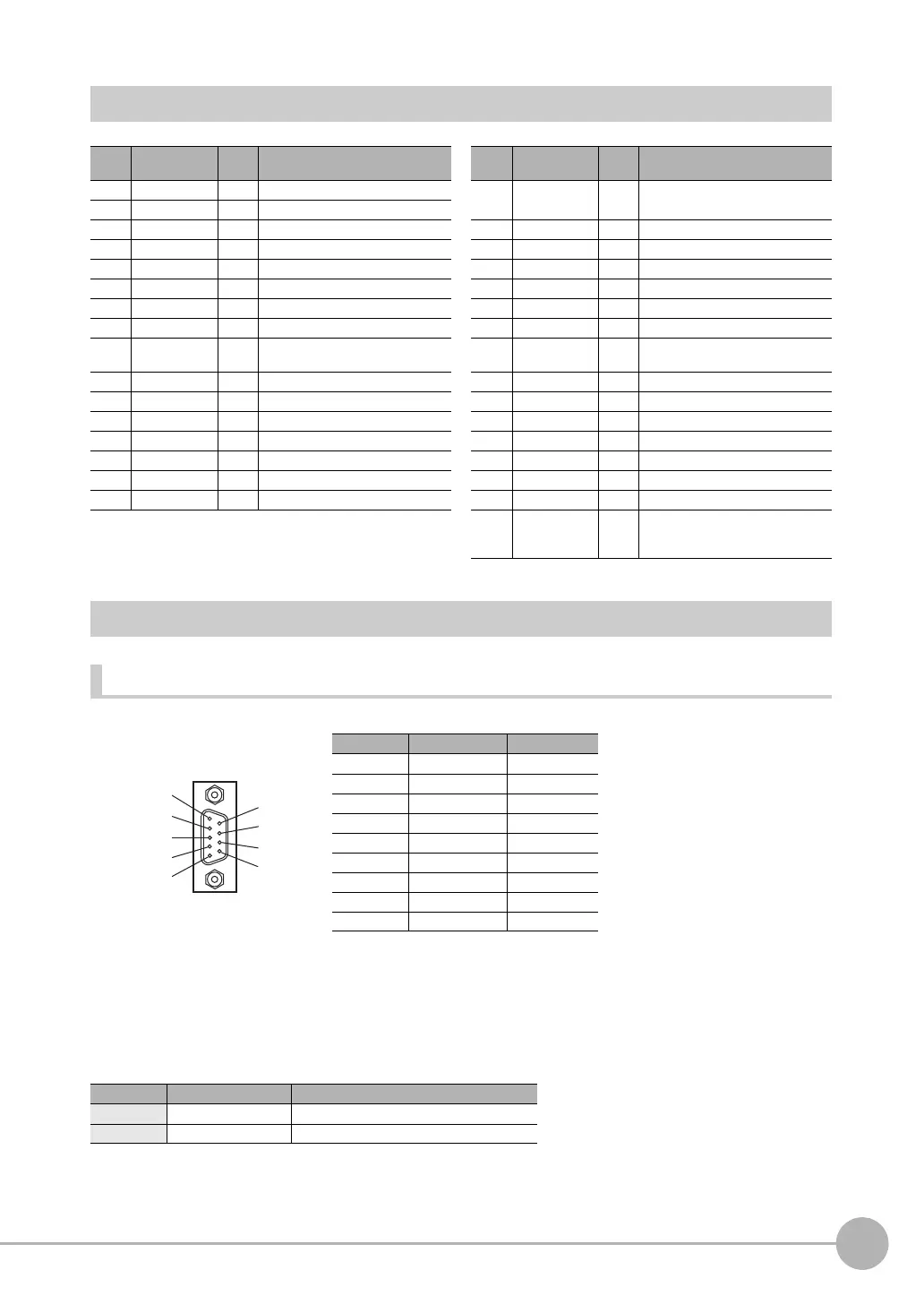
FQ-SDU20/SDU25 RS-232C Pin Signal Names
RS-232C Connector
Pin numbers will depend on the external device being connected. Refer to the manual for the personal
computer or PLC being connected.
Use a compatible connector.
• Recommended items
Pin Signal IN/
OUT
Function Pin Signal IN/
OUT
Function
1 IN0 IN Command input 17 COMIN0 - Input signal common (RESET
and IN0 to IN5)
2 IN1 IN Command input
3 IN2 IN Command input 18 COMIN1 - Input signal common (TRIG)
4 IN3 IN Command input 19 TRIG IN Measurement trigger input
5 IN4 IN Command input 20 NC
*1
-
6 IN5 IN Command input 21 NC
*1
-
7NC
*1
- 22 RESET IN Reset input
8NC
*1
-23NC
*1
-
9NC
*1
- 24 ACK OUT Command execution completed
flag
10 NC
*1
- 25 RUN OUT ON during measurement mode
11 NC
*1
- 26 BUSY OUT ON during process execution
12 NC
*1
- 27 OR OUT Overall judgement result
13 NC
*1
- 28 ERROR OUT ON during error
14 NC
*1
- 29 STGOUT OUT Strobe trigger output
15 NC
*1
- 30 SHTOUT OUT Shutter trigger output
16 NC
*1
-31NC
*1
-
32 COMOUT0 - Output signal common (ACK,
RUN, BUSY, OR, ERROR,
STGOUT, and SHTOUT)
Manufacturer Model
Socket OMRON Corporation XM3D-0921
Hood OMRON Corporation XM2S-0913
1
2
3
4
5
6
7
8
9
Pin No. Signal name Function
1 NC Not connected
2 RD For RS-232C
3 SD For RS-232C
4 NC Not connected
5 GND Signal ground
6 NC Not connected
7 NC Not connected
8 NC Not connected
9 NC Not connected