Adjusting the Images That Were Taken
FQ2 User’s Manual
87
3
Taking Images
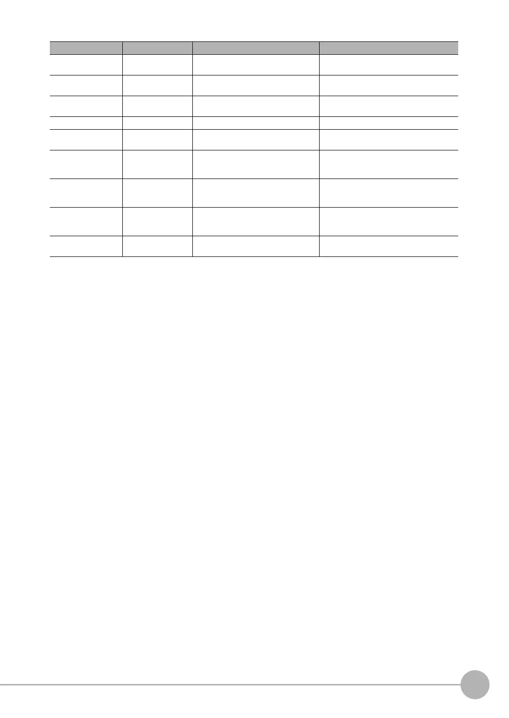
Y0 Edge 0 position Y This is the Y coordinate of the measured
edge 0 position.
−99,999.9999 to 99,999.9999
X1 Edge 1 position X This is the X coordinate of the measured
edge 1 position.
−99,999.9999 to 99,999.9999
Y1 Edge 1 position Y This is the Y coordinate of the measured
edge 1 position.
−99,999.9999 to 99,999.9999
TH Angle (edge angle) This is the measured angle. −180 to 180
SX0 Edg0 ref. pos. (edge 0
reference position X)
This is the X coordinate of the edge 0
position when it was registered.
−99,999.9999 to 99,999.9999
SY0 Edg0 ref. pos. Y (edge
0 reference position
Y)
This is the Y coordinate of the edge 0
position when it was registered.
−99,999.9999 to 99,999.9999
SX1 Edg1 ref. pos. X (edge
1 reference position
X)
This is the X coordinate of the edge 1
position when it was registered.
−99,999.9999 to 99,999.9999
SY1 Edg1 ref. pos. Y (edge
1 reference position
Y)
This is the Y coordinate of the edge 1
position when it was registered.
−99,999.9999 to 99,999.9999
STH Reference angle This is the angle when the edge was reg-
istered.
−180 to 180
Expression text string Data name Description Data range