1 - 19
1 Overview
NX-series Safety Control Unit User’s Manual (Z930)
1-5 Commissioning Procedures
1
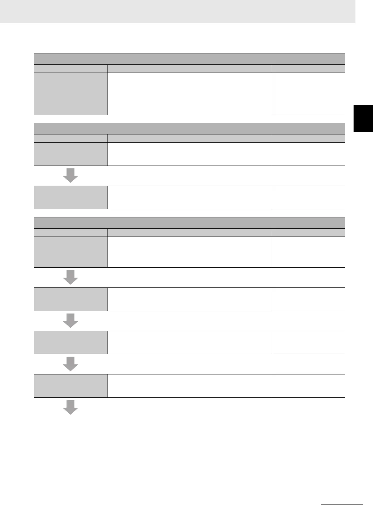
1-5-2 Detailed Procedures
Step 2. Hardware Design
Step Description Reference
Step 2-1 Determining Wir-
ing for Communications,
Power Supply, and Exter-
nal I/O Devices
Determine the wiring for the communications network, power
supply, and safety I/O devices.
Section 3 Part Names and
Functions
Manuals for specific Com-
munications Coupler Units
NX Unit User’s Manuals
Step 3. Calculating and Verifying Safety Response Performance
Step Description Reference
Step 3-1 Calculating Safety
Reaction Time and Safety
Distance
Calculate the safety reaction times and use them to find the
safety distances.
Section 4 Calculating
Safety Reaction Times
Step 3-2 Verifying Fulfill-
ment of Required Specifi-
cations
Check to see if requirements are met. If requirements are not
met, reconsider the designs again starting with the system
design.
Section 4 Calculating
Safety Reaction Times
Step 4. Software Settings and Programming
Step Description Reference
Step 4-1 Creating the
Safety Control System
Configuration
On the Sysmac Studio, configure the Communications Coupler
Units, Safety CPU Units, and Safety I/O Units.
6-3 Controller Configura-
tion and Setup of the
Safety Control Units on
page 6-4
Step 4-2 Setting Up and
Checking the Safety Pro-
cess Data Communications
Check the settings for the safety process data communications
and make any necessary changes.
6-4 Setting Up the Safety
Process Data Communica-
tions on page 6-10
Step 4-3 Assigning Safety
I/O Terminals to the Con-
nected Devices
On the parameter setting tab page for the Safety I/O Units,
select the safety I/O devices that are connected to the safety I/O
terminals.
6-5 Setting the Safety Input
and Output Functions on
page 6-12
Step 4-4 Assigning Device
Variables to I/O Ports
Register the device variables in the global variable table. (You
can use either user-defined or automatically assigned variable
names.)
6-6 Registering Device
Variables on page 6-15