5 Motion Control Parameters
5-12
NJ/NX-series CPU Unit Motion Control User’s Manual (W507)
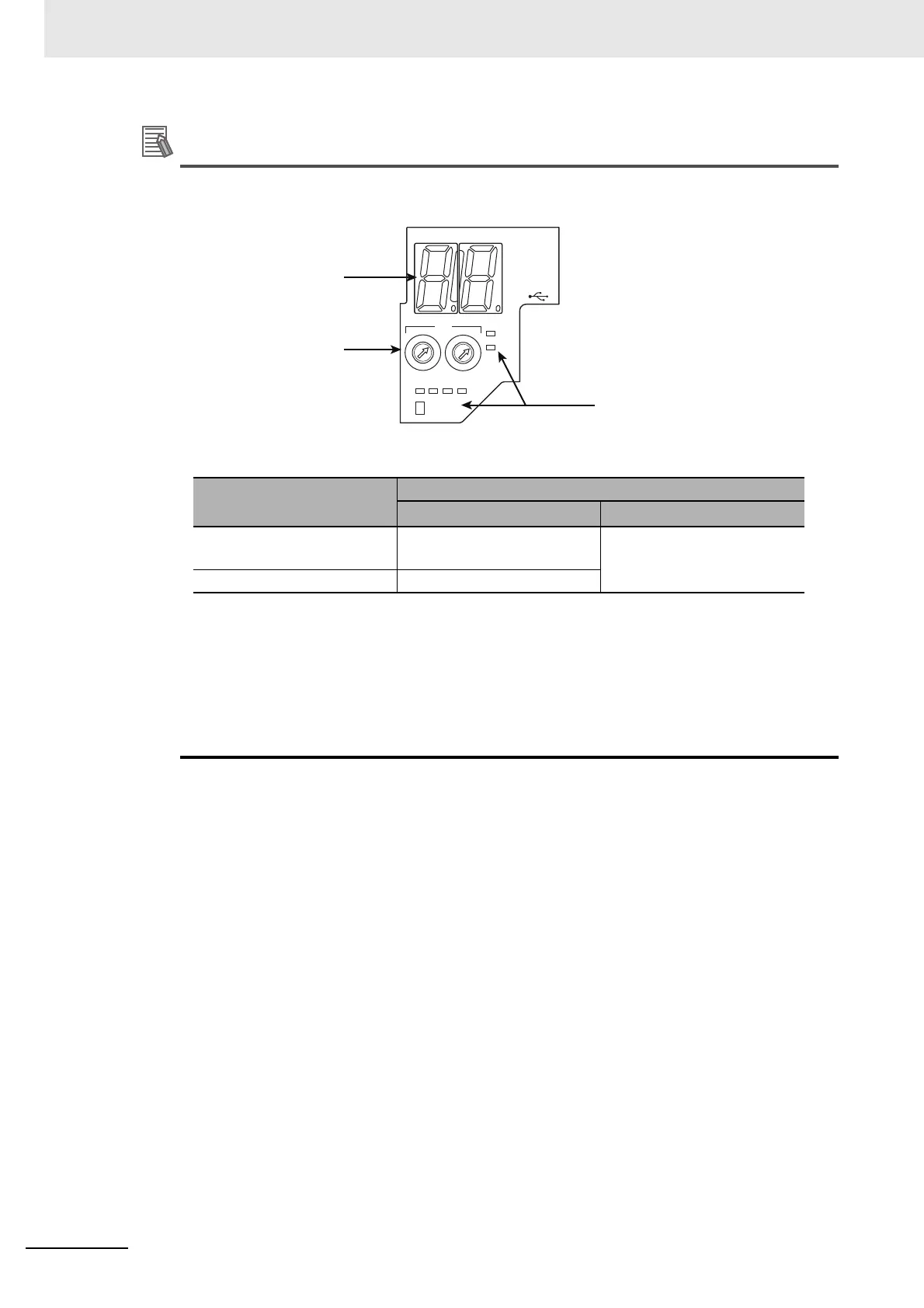
• The following example shows the EtherCAT device’s node address setting for an OMRON 1S-
series Servo Drive with built-in EtherCAT communications.
• The rotary switches in the display area on the Servo Drive are used to set the EtherCAT node
address.
*1 The value set from the Sysmac Studio will be used for all non-OMRON slaves, regardless of any setting
at the slave.
*2 For the NJ-series CPU Unit, the set value is 1 to 192. However, only for the NJ101 CPU Unit, the maxi-
mum number of slaves which can be connected is 64 slaves.
For the NX102 CPU Unit, the set value is 1 to 192, and the maximum number of slaves which can be
connected is 64 slaves.
For the NX1P2 CPU Unit, the set value is 1 to 192, and the maximum number of slaves which can be
connected is 16 slaves.
Rotary switch setting
Node address setting range
OMRON slaves
Non-OMRON slaves
*1
00 Value set from the Sysmac
Studio (1 to 512
*2
)
Value set from the Sysmac
Studio (1 to 512
*2
)
01 to 99 Node address switch setting
3
4
5
CN7
ID
x16 x1
2
0
1
2
3
4
5
6
7
8
9
A
B
C
D
E
F
0
1
2
3
4
5
7
8
9
A
B
C
D
E
F
6
7-segment display
Status indicators
ID switch

 Loading...


