9 Motion Control Functions
9-18
NJ/NX-series CPU Unit Motion Control User’s Manual (W507)
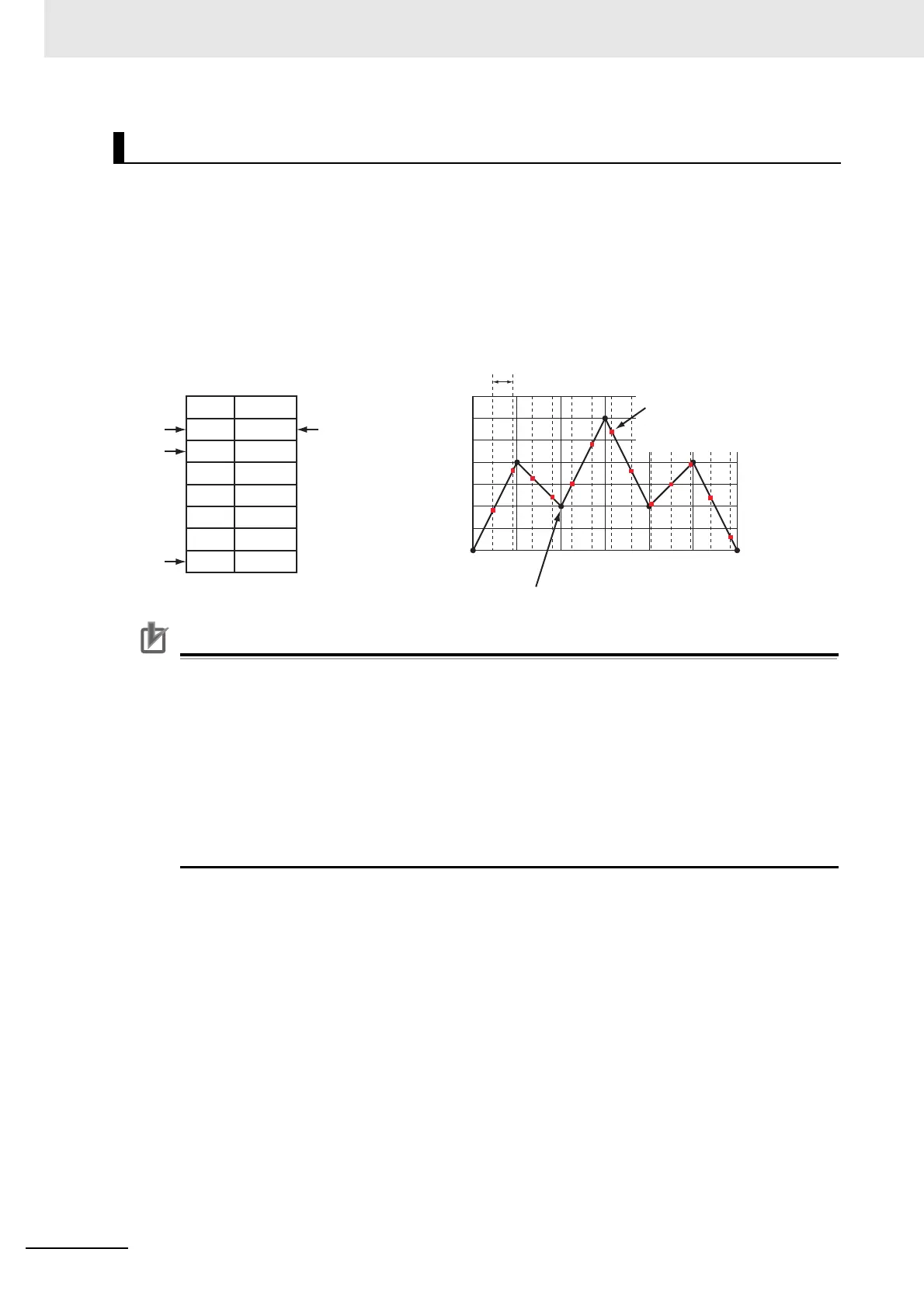
The MC Function Module defines a single element of data consisting of the phase of the master axis
and the displacement of the slave axis as one cam data. A cam table is defined as the combination of
multiple sets of cam data. The cam table is created with the Cam Editor in the Sysmac Studio. You can
modify cam data in the cam table from the user program.
The phases and displacements in the cam data that makes up the cam table are represented as rela-
tive distances from the start point 0.0. During cam operation, the command position sent to the slave
axis is the displacement determined by interpolating linearly between the two cam data elements adja-
cent to the phase of the master axis. The more cam data there is in the cam table, the more accurate
the trajectory and the smoother the cam profile curve will be.
Precautions for Correct UsePrecautions for Correct Use
• Make sure that the cam data is arranged in the cam table so that the phases are in ascending
order. An instruction error occurs if a cam operation instruction is executed when the phases
are not in ascending order.
• Cam data variables are global variables. You can therefore access or change the values of
cam data variables from more than one task. If you change the values of cam data variables
from more than one task, program the changes so that there is no competition in writing the
value from more than one task.
• If you use exclusive control of global variables between tasks for a cam data variable, do not
use the cam data variable for motion control instructions in a task that does not control the
variable. An Incorrect Cam Table Specification (event code: 54390000 hex) will occur.
Cam Tables
Phase
Displacement
Cam data (black dots on the line).
Phase
Command position during
cam operation
1 cycle
Displacement
Cam end point
Cam start point
Cam data
Cam table
0 60 120 180 240 300 360
0
50
100
150
200
250
300
350
00
60 200
120 100
180 300
240 100
300 200
360 0
0
1
2
3
4
5
6
Cam data index
The phase is calculated from the master
axis position each cycle. The linear
interpolation of cam data is used to
calculate the displacement from the phase.
(These are the red dots on the line.)

 Loading...


