Appendices
A-10
NJ/NX-series CPU Unit Motion Control User’s Manual (W507)
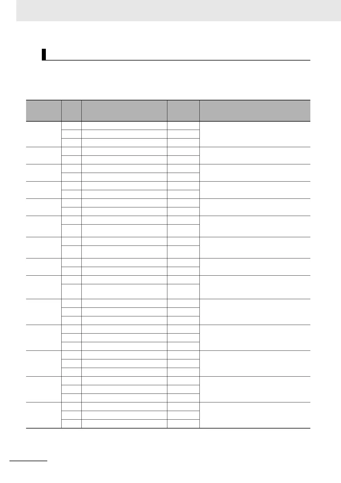
The OMRON 1S-series Servo Drive settings required to use the control functions of the MC Function
Module are listed in the following table.
Consult the manual for your Servo Drive and set all related objects for the Servo Drive functions that
you are going to use.
*1 With a CPU Unit of unit version 1.10 or earlier, you cannot operate OMRON 1S-series Servomotors in the maximum rota-
tion speed. To operate the 1S-series Servomotors in the maximum rotation speed, set the electronic gear ratio to 2:1 or
greater.
Object Settings
Index
Sub-
index
Name
Recom-
mended
setting
Description
3001 hex --- Machine --- The gear ratio on the Servo is 1:1. Set the user
unit on the Controller.
*1
05 hex Electronic Gear Ratio Numerator 1
06 hex Electronic Gear Ratio Denominator 1
3330 hex --- Torque Limit --- Use 60E0 hex and 60E1 hex as the torque
limit values when PCL and NCL are OFF.
01 hex Switch Selection 2
3A00 hex --- Homing --- Use 0 as the offset value on the Servo.
06 hex Encoder Home Offset 0
3B10 hex --- Drive Prohibit --- Disable the drive prohibit input at the Servo. It
is processed by the Controller.
01 hex Enable 0
3B11 hex --- Software Limits --- Disable both the positive and negative soft-
ware limits.
01 hex Enable Selection 0
3B30 hex --- Touch Probe Function 1 --- Set this as follows: Touch probe1 = External
latch signal 1, Touch probe2 = External latch
signal 2.
01 hex Latch 1 Trigger Selection 1
3B31 hex --- Touch Probe Function 2 --- Set this as follows: Touch probe1 = External
latch signal 1, Touch probe2 = External latch
signal 2.
01 hex Latch 2 Trigger Selection 2
4020 hex --- Warning Customization --- Set this to automatically reset warnings when
the cause is removed.
04 hex Warning Hold Selection 0
4510 hex --- Encoder --- Use as absolute encoders.
Ignore multi-rotation counter overflow.
01 hex Absolute Encoder Operation Selec-
tion
2
4630 hex --- Positive Drive Prohibit --- Assign the Positive Drive Prohibit to the gen-
eral-purpose input 2 (IN2) as a negative logic
(NC input).
01 hex Port Selection 2
02 hex Logic Selection 1
4631 hex --- Negative Drive Prohibit --- Assign the Negative Drive Prohibit to the gen-
eral-purpose input 3 (IN3) as a negative logic
(NC input).
01 hex Port Selection 3
02 hex Logic Selection 1
4632 hex --- External Latch Input 1 --- Assign the External Latch Input 1 to the gen-
eral-purpose input 7 (IN7) as a positive logic
(NO input).
01 hex Port Selection 7
02 hex Logic Selection 0
4633 hex --- External Latch Input 2 --- Assign the External Latch Input 2 to the gen-
eral-purpose input 8 (IN8) as a positive logic
(NO input).
01 hex Port Selection 8
02 hex Logic Selection 0
4634 hex --- Home Proximity Input --- Assign the Home Proximity Input to the gen-
eral-purpose input 4 (IN4) as a positive logic
(NO input).
01 hex Port Selection 4
02 hex Logic Selection 0

 Loading...


