A-25
Appendices
NJ/NX-series CPU Unit Motion Control User’s Manual (W507)
A-3 Connecting to Encoder Input Terminals
A
A-3-2 Settings for Encoder Input Terminals
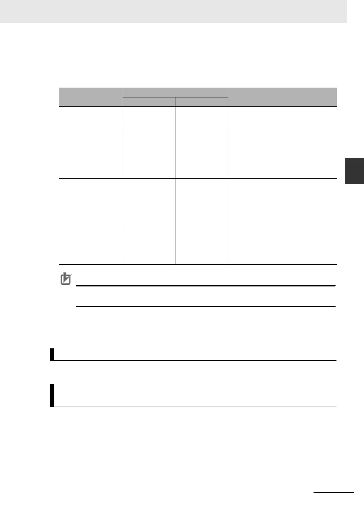
Input Settings (Servo Drive to Controller)
This is the status data from the Encoder Input Terminal to the MC Function Module. The default set-
tings in the Sysmac Studio are listed in the following table. (Required objects are marked with a
star.)
Precautions for Correct UsePrecautions for Correct Use
• If you change the settings, make sure that the desired operations are performed for the MC
Function Module and process data settings.
Digital Input Settings
Settings are not required to use an encoder axis.
There are no objects that you must set at the Encoder Input Terminal.
The Modulo Minimum Position Setting Value and Modulo Maximum Position Setting Value in the Servo
Drive Settings in the axis parameters of the MC Function Module must agree with the maximum value
setting of the ring counter in the Encoder Input Terminal.
The Modulo Minimum Position Setting Value and Modulo Maximum Position Setting Value are set on
the Servo Drive Settings View on the Sysmac Studio.
The settings are as follows:
Function name
Process data
Description
Channel 1 Channel 2
Position actual
value
4010 hex-01.0
(Position Value)
4010 hex-02.0
(Position Value)
Store the current values from the counters.
Set the objects given at the left for each
channel.
Touch probe posi-
tion 1 position value
4012 hex-01.0
(Latch Value A)
4012 hex-02.0
(Latch Value A)
This is the latched position for latch 1.
Store the values of latch positions A. You
must map these objects to use the touch
probe function, i.e., to use the MC_Touch-
Probe (Enable External Latch) instruction.
Set the objects given at the left for each
channel.
Touch probe posi-
tion 2 position value
4013 hex-01.0
(Latch Value B)
4013 hex-02.0
(Latch Value B)
This is the latched position for latch 2.
Store the values of latch positions B. You
must map these objects to use the touch
probe function, i.e., to use the MC_Touch-
Probe (Enable External Latch) instruction.
Set the objects given at the left for each
channel.
Status of Encoder’s
Input Slave
4030 hex-01.0
(Status Bits)
4030 hex-02.0
(Status Bits)
Store the status bits. You must map these
objects to use the touch probe function,
i.e., to use the MC_TouchProbe (Enable
External Latch) instruction. Set the objects
given at the left for each channel.
Object Settings in the Encoder Input Terminals
Relationship between the MC Function Module and the Ring
Counter of an Encoder Input Terminal

 Loading...


