3 Configuring Axes and Axes Groups
3-6
NJ/NX-series CPU Unit Motion Control User’s Manual (W507)
Required Settings to Perform a Servo Drive Test Run from the Sysmac Studio
Make the following settings to operate an EtherCAT-connected Servo Drive or other device using
the MC test run function of the Sysmac Studio.
*1 Set this parameter when using the NX701 CPU Unit.
*2 Set this parameter when using the NX102 CPU Unit and NX1P2 CPU Unit.
*3 To use the axis as a motion control axis, select All. To use the axis as a single-axis position control axis, select
Single-axis position control only.
*4 For example, if the encoder resolution is 10,000 pulses/rotation, set 10,000.
*5 A CPU Unit with unit version 1.11 or later and Sysmac Studio version 1.15 or higher are required to use this
parameter.
Precautions for Correct UsePrecautions for Correct Use
• Select the appropriate values based on the machine’s operating conditions for parameters
such as the maximum velocity, maximum acceleration/deceleration, or stop settings when the
motor is actually operated.
• OMRON 1S-series Servo Drives and G5-series Servo Drives can be set to specific node
addresses by using the rotary switches on the front panels. If the rotary switches are set to 00,
the node address will be determined by the settings made in the EtherCAT Editor of the Sys-
mac Studio. If the rotary switches are set to 00 for all connected Servo Drives, errors will not
occur even if the Servo Drive’s connection position is changed. Set the node addresses on the
rotary switches to assign specific Servo Drives for each machine control.
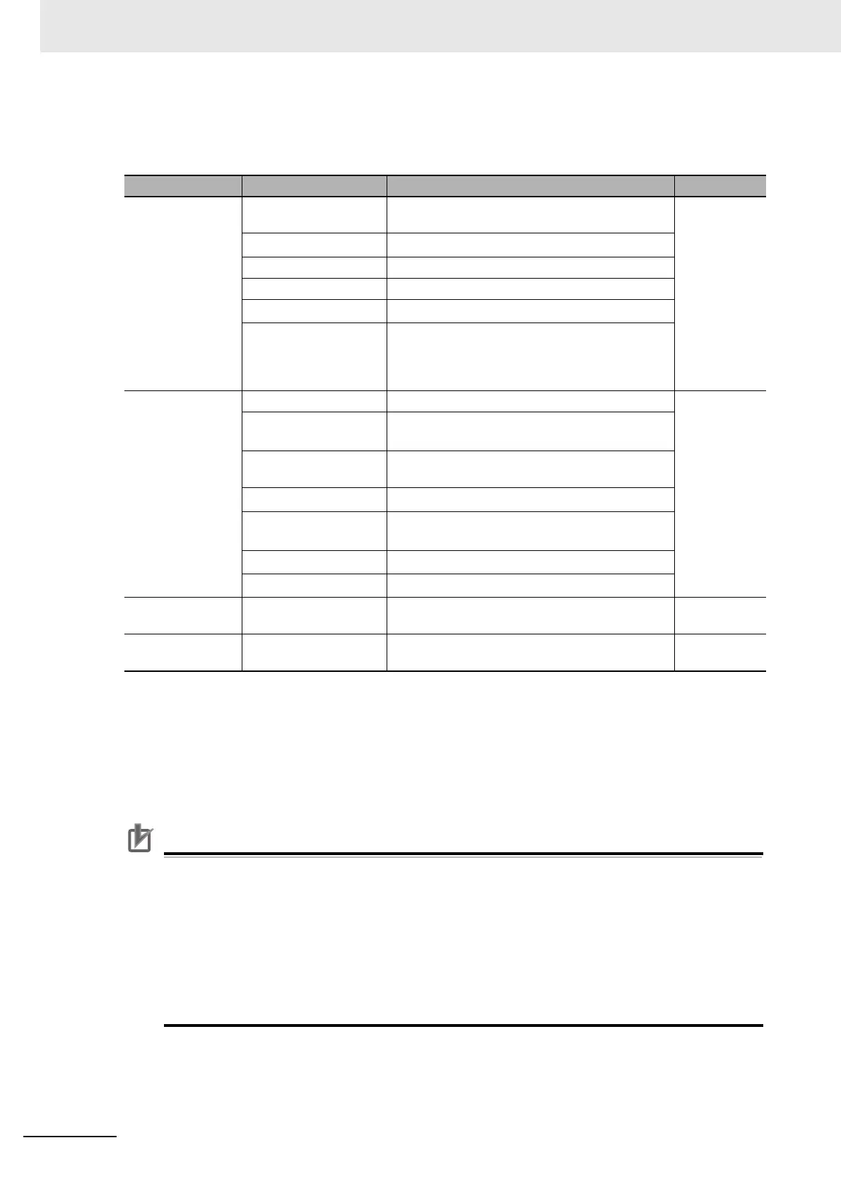
Classification Parameter name Setting Page
Axis Basic Set-
tings
Axis Number The numbers are assigned in the order that the
axes are added.
P. 5 - 7
Motion Control
*1
Select Primary periodic task.
Axis Use Select Used axis.
Axis Type Select Servo axis.
Control Function
*2
Select All.
*3
Input Device/Output
Device
Specify the node address of the EtherCAT slave
device that is assigned to the axis. The Node
Address parameter cannot be selected if the Axis
Type parameter is set to use a virtual axis.
Unit Conversion
Settings
Unit of Display Select the display unit (mm, degrees, etc.). P. 5-13
Command Pulse Count
Per Motor Rotation
Set the number of command pulses per motor
rotation according to the encoder resolution.
*4
Work Travel Distance
Per Motor Rotation
Set the workpiece travel distance per motor rota-
tion according to the machine specifications.
Reducer Use
*5
Specify whether to use the reducer setting or not.
Work Travel Distance
Per Rotation
*5
Set the work travel distance per rotation.
Work Gear Ratio
*5
Set the gear ratio for the workpiece.
Motor Gear Ratio
*5
Set the gear ratio of the motor.
Position Count
Settings
Count Mode Set this parameter according to the machine
specifications.
P. 5 - 2 5
Limit Settings Software Limits Set this parameter according to the device speci-
fications.
P. 5 - 2 5

 Loading...


