Medium & Heavy Payload Series-Hardware Installation Manual TM12/14 Series Hardware Version: 3.2 72
(2 wires)
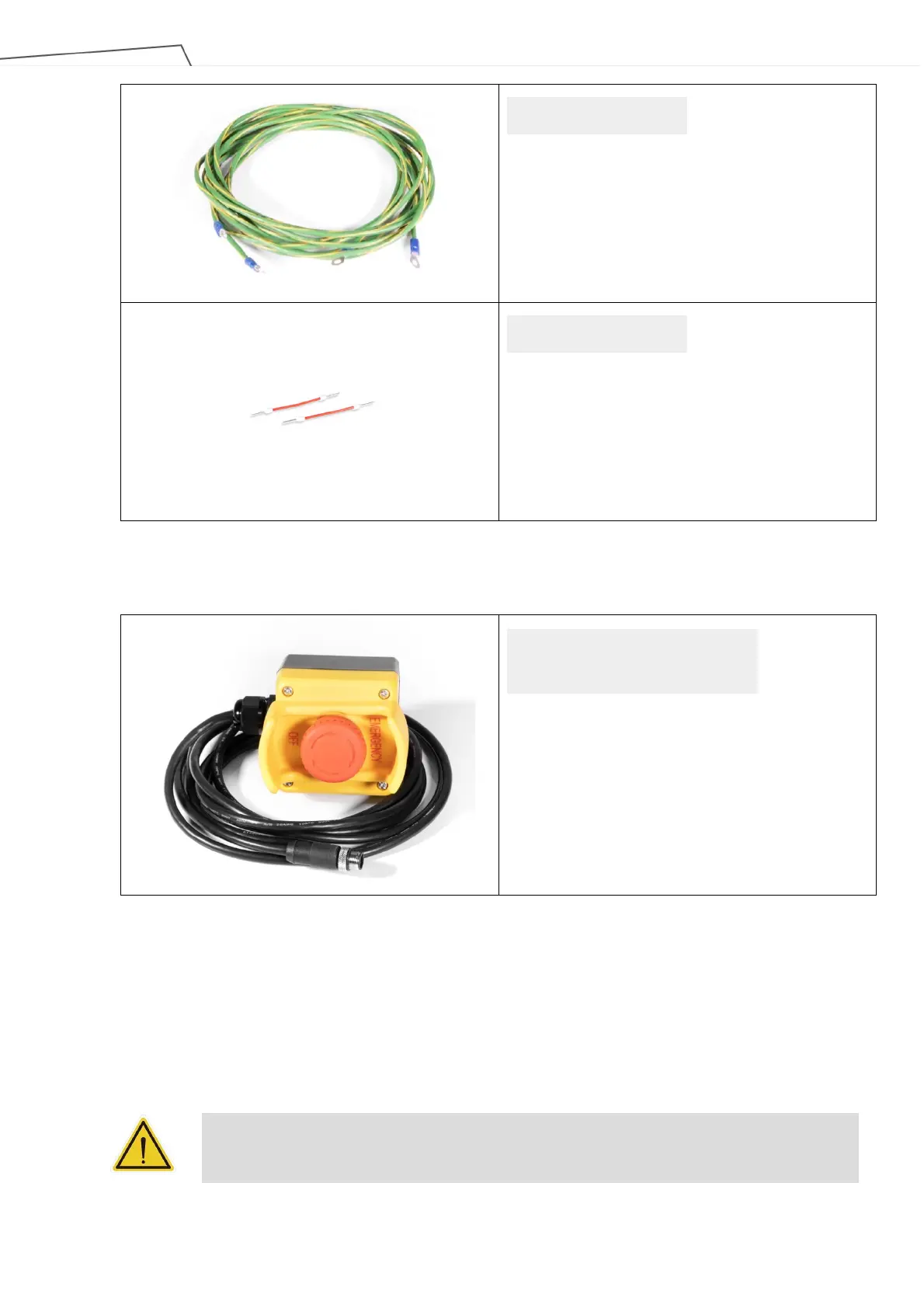
Cable Length: 300 cm
(1 pair)
Wire Length: 3 cm
Table 20: The Control Box Carton Contents
The SEMI Emergency OFF Switch carton contains:
(1 pack)
Cable length: 300 cm
Table 21: The SEMI Emergency OFF Switch Carton Contents
6.4 Installing Your Robot
The TM Robot arm cannot stand independently after being removed from the carton. Therefore, prepare the
mounting base with the corresponding holes as described in 4.2.1.6 Robot Arm Installation, and follow the
instructions below to install the robot.
WARNING:
At the installation site, at least two people should simultaneously perform installation of the
robot; otherwise you risk robot arm damage or personal injury. Do not install the robot alone.
Ground Wire
Jumper Wire
SEMI Emergency OFF Switch