5-26
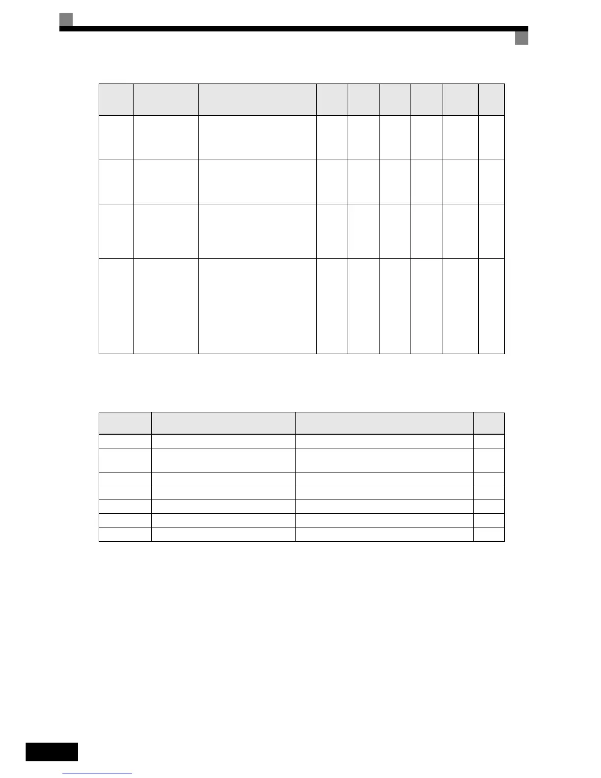
H3-09 Settings
H3-10 Terminal A2 gain
Sets the value of the function sig-
nal when 10 V (20 mA) is input
as a percentage of the maximum
value.
0.0 to
1000.0
100.0% Yes A 419H 6-21
H3-11 Terminal A2 bias
Sets the value of the function sig-
nal when 0 V (0/4 mA) is input as
a percentage of the maximum
value.
-100.0
to
+100.0
0.0% Yes A 41AH 6-21
H3-12
Analog input fil-
ter time constant
Sets input filter time constant for
the two analog input terminals
(A1 and A2).
Effective for noise suppression
etc.
0.00 to
2.00
0.30
sec.
No A 41BH 6-21
H3-13
Terminal A1/A2
switching
Selects on which terminal the
main frequency reference can be
input.
0: Use analog input 1 on terminal
A1 for main frequency refer-
ence.
1: Use analog input 2 on terminal
A2 for main frequency refer-
ence.
0 or 1 0 No
A
*1
41CH 6-21
*1. Parameter is also available in Quick Programming Mode when PI controller is enabled, otherwise parameter is only available in Advanced Program-
ming Mode.
*2. Setting switched to “B” when PI controller is enabled
Setting
Value
Function Contents (100%) Page
0 Frequency bias Maximum output frequency 6-22
2
Auxiliary frequency reference (is used as
frequency reference 2)
Maximum output frequency 6-7
B PI feedback Maximum output frequency 6-87
D Frequency Bias 2 Maximum output frequency 6-22
E Motor temperature input – 6-35
16 PI differential input Maximum output frequency 6-87
1F Analog input not used. – –
Parame-
ter Num-
ber
Name Description
Setting
Range
Factory
Setting
Change
during
Opera-
tion
Access
Level
MEMO-
BUS
Register
Page