Final Hardware Actions
Hardware Installation 3-27
Task 2 Connect Cables to the Tape Drive Assembly and Power Supply
1. For each installed power supply, connect the power cord to the AC receptacle on
the power supply and connect the power cord to the power distribution unit in the
rack.
A list of power cord part numbers is available in the StorageTek SL150 Modular Tape
Library Systems Assurance Guide.
2. For each installed tape drive, connect the interface cable(s) to the tape drive
interface port(s). Attach a label indicating the tape drive position in the module
and port to ensure proper connection after a service action.
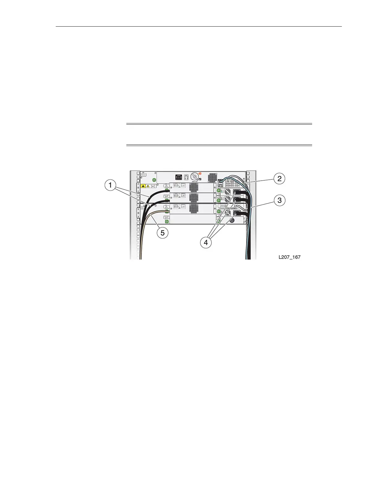
Figure 3–27 Initial Cabling
Illustration Legend:
1 - Tape Drive Fibre Channel Cable
2 - Expansion Cable
3 - Ethernet Cable (Net Mgt Port 1)
4 - Power Supply Cord
5 - Tape Drive Serial Attached SCSI (SAS) Cable
Task 3 Connect the Network Port
1. Locate the NET MGT area of the base module (above the power supply and left of
the Module Output ports).
2. Insert the Ethernet cable plug in the top port, designated witha1onthechassis.
3. Attach a label to the cable indicating the network port to ensure proper connection
after a service action.
Task 4 Align and Dress the Cables and Cords
1. Gather cable slack to the outside edge of the expansion module, if necessary.
2. Wrap the hook and loop strap around the cables and cords.
3. Stow excess cord and cable length into the cavity between the rack stile and the
side cover.
Note: The interface port is located on the left side of the drive tray
assembly (as viewed from the rear of the library).

 Loading...