SECTION 1: INTRODUCTION AND EQUIPMENT DESCRIPTION
5 REI OSC-5000E
Antenna Panel
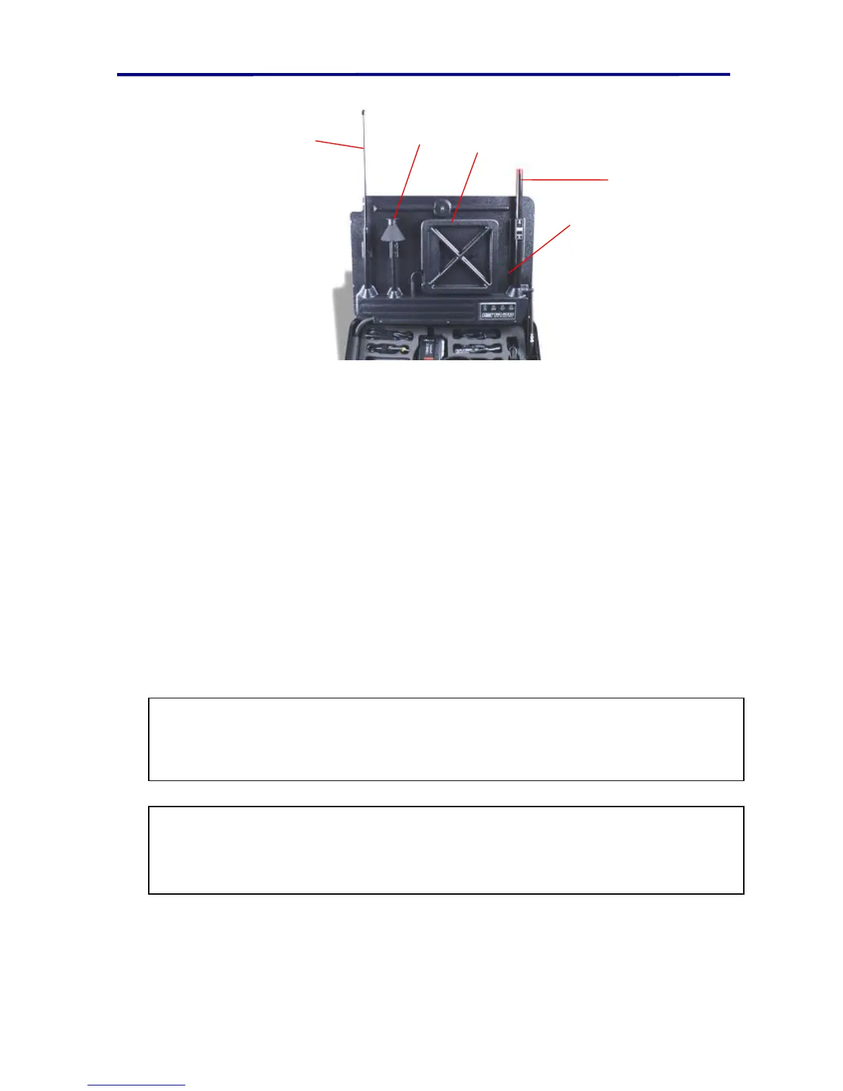
FIGURE 4 ANTENNA PANEL
1
2
3
5
4
The OSCOR antenna panel is an integrated package that automatically selects the
correct antenna based on the operating frequency.
1. Active Whip Antenna - GaAs FET preamplifier and telescoping whip provide high
sensitivity and wide 0.5-1500 MHz frequency coverage. *
2. Discone Antenna - Covers a 1500-3000 MHz frequency range. *
3. Balanced Loop Antenna - contains an active amplifier and covers 10 to 500 kHz.
Can also be removed from the antenna array panel and placed at a remote location.
4. Infrared Detector - when extended, the IR DETECTOR will observe a 360° view and
detect IR energy with a wavelength of 850-1050 nM and modulation of 15 kHz to 5
MHz.
5. Status Indicators - shows the antenna currently selected.
6. AC VLF (not shown in picture) - OSCOR AC power cord is also a probe (called AC
VLF probe). It is used to test wiring for carrier transmitters. It can test any pair of
conductors for carrier current (provided the voltage level is less than 250 volts).
7. Microwave Downconverter (not shown in picture) – Provides observation of
frequencies from 3 GHz to 21 GHz.
*WARNING: The ACTIVE WHIP ANTENNA and DISCONE contain circuitry that
can be damaged by electrostatic discharge. If electrostatic conditions exist, be sure
to touch the OSCOR main chassis before touching the WHIP or DISCONE.
WARNING: The AC power cord is designed to handle voltage levels up to 250
volts. Do not exceed this limit, or the unit may be damaged. (If this limit is
exceeded and your unit is damaged, return it to REI or your dealer for repair.)