SECTION 3: OSCOR MANUAL OPERATION
REI OSC-5000E 64
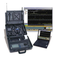
FIGURE 42 OTL RANGING SCREEN
10. After all measurements have been made, press the MENU button (labeled
LOCATE) to view the position of the microphone. The positions indicated on
the screen are referenced to the OSCOR connector tray expansion port
connector. The accuracy of the triangulated position may vary depending on
the consistency of the range measurements and the position of the
eavesdropping device.
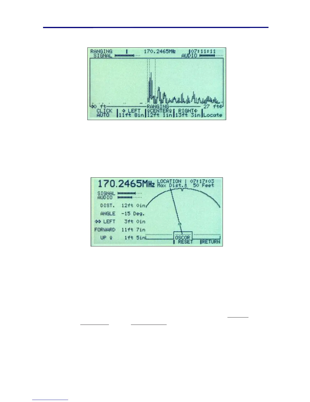
FIGURE 43 OTL LOCATION SCREEN
TECHNICAL NOTE: It is very important to hold the clicking device in the correct position
while making measurements. Position errors of only a few inches at the clicking device
may result in errors of several feet when locating a bugging device.
TECHNICAL NOTE: If the above method results in only very small spikes or no spikes at
all, but the signal provides confirmed demodulated audio, try the following:
Adjust the range of the screen to its maximum value (60 ft/18 meters).
1. Try different bandwidths and demodulators (see pages 29 Receiver
Bandwidths and 40 Demodulators).
2. Move to another location in the room, and try again.