SECTION 1: INTRODUCTION AND EQUIPMENT DESCRIPTION
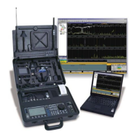
REI OSC-5000E 6
Power System
Power is obtained in one of three ways:
1. AC power of 115/230 VAC
2. Internal Rechargeable 12 VDC Battery
3. External 12-18 VDC input
NOTE: Whenever possible, it is best to use AC power to keep the battery charged and
to allow the AC VLF to scan for carrier current eavesdropping devices.
AC Power
The internal AC power supply actively monitors the voltage level of the AC power input.
The green LED (labeled “AC ~”) will show when there is sufficient power.
WARNING: Be sure the voltage selector switch is set to the proper
input voltage (115 or 230 VAC) before operation.
The green LED labeled “AC Power” indicates proper AC voltage. If the voltage selector is
set to “115 VAC” and the unit is plugged into 230 VAC, the unit will not be damaged,
but the green LED will go dark and you must unplug the unit to cool down for
approximately 30 minutes for the internal protection circuit to cool down.
International AC Power
The AC power receptacle is a worldwide IEC-320 standard and will accept right-angle
style power cables for most countries. If the appropriate cord or adapter is not readily
available, the cord provided can be fitted with another plug.
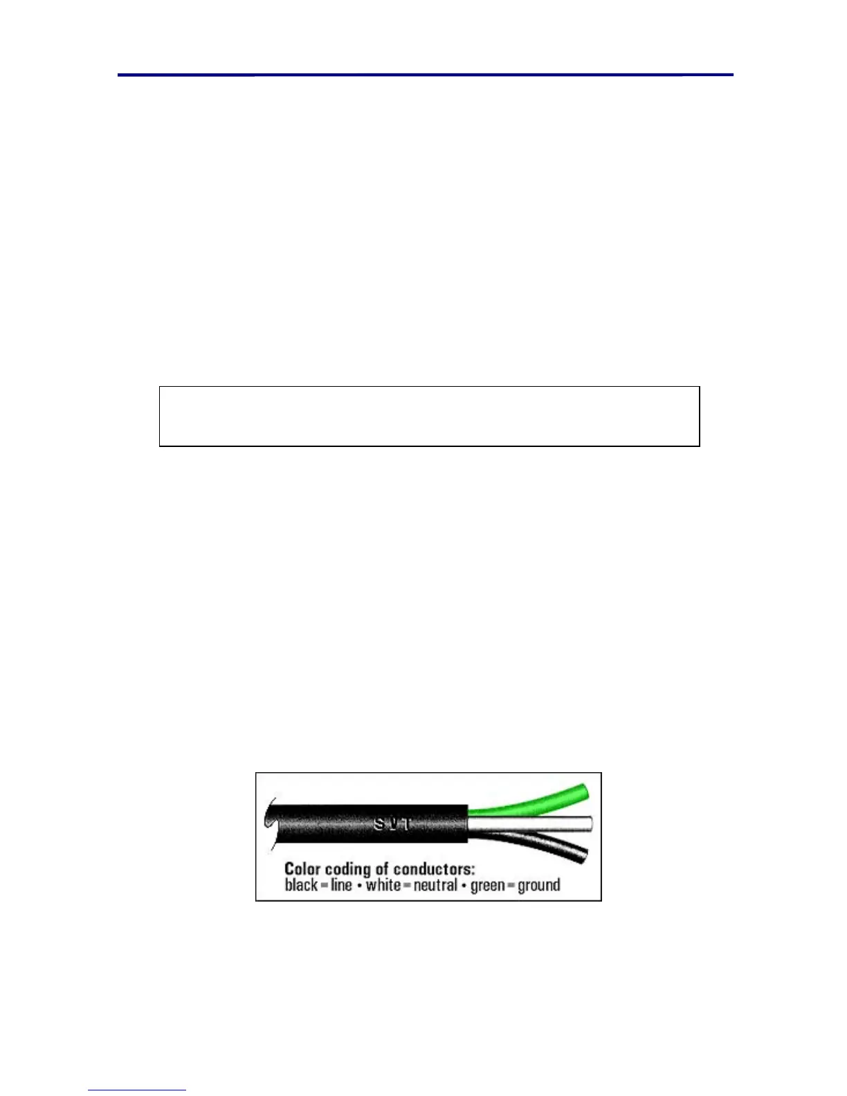
Observe the wiring conventions for the connector of your choice, and follow the color
assignments of the USA/Canada power cord supplied with the OSC-5000. Although the
use of earth ground is always preferable, it is not essential that your power system
provide that connection. Contact REI or your dealer with your particular power
requirements.
FIGURE 5 AC POWER CONNECTOR WIRING
NOTE: Battery charging and other internal functions are automatic.