SECTION 3: OSCOR MANUAL OPERATION
63 REI OSC-5000E
TECHNICAL NOTE: The single click method provides only one click per range
measurement. The multiple click method integrates multiple clicks for a very reliable
measurement that filters out any extraneous noise. Therefore, the single click method
will work well only in a very quiet room. However, the single click method is
advantageous because it is more covert than the multiple click method. The multiple
click method is very noisy and may alert the eavesdropper.
7. Press (and release) F2, F3, or F4 to initiate the clicking device. The clicking sound
should be continuous if F1 is labeled “AUTO”.
Adjust the volume of the clicking with the UP/DOWN buttons.
Adjust the screen width with the EXPAND/NARROW buttons. For best
accuracy, the screen should be at the minimum range (Narrow) that still allows
the audio spikes to be visible.
8. Adjust the directional sound characteristics by using the parabolic reflector
attached to the OTL-5000 device. When the first spike on the display is
maximized, the OTL-5000 device is pointing in the direction of the microphone.
The OSCOR in this mode displays the range to the bug. The spikes on the screen
represent the sound of the clicking being received by the bug. The multiple spikes
are the echoes from the clicking. The rising edge of the very first spike is the direct
path to the bug and should be used for each range measurement.
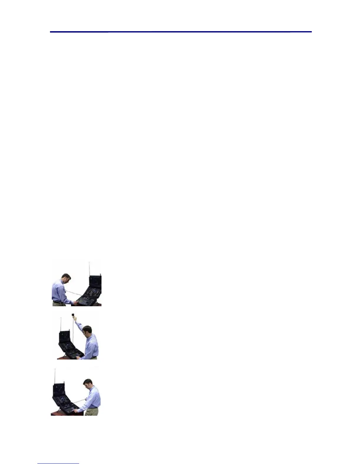
9. The range is measured in three positions (represented by left, center, and right) by
placing the cursor at the rising edge of the first spike (using the Rotary Dial). The
range measurement is “locked” into memory by pressing F2, F3, or F4 for each
respective range measurement. The range measurement is based on the location
of the cursor when pressing F2, F3, or F4. Special care should be taken in the
OTL position when making measurements.
• Left position - stretch the OTL-5000 device directly left
(over the AC power connector) until the cable is parallel to
the OSCOR main panel.
• Center position - stretch the OTL-5000 device directly
vertical until the cable is perpendicular to the OSCOR main
panel.
• Right position - stretch the OTL-5000 device directly right
(over the OSC-5000 printer paper) until the cable is
parallel to the OSCOR main panel.
FIGURE 41 TRIANGULATE AND LOCATE POSITIONS