SECTION 3: OSCOR MANUAL OPERATION
61 REI OSC-5000E
3. Press the THREAT button and then F1 to turn on the locator probe function.
4. Adjust the volume so that you can hear the locator tone.
5. Adjust the squelch level so that the squelch is just above the signal level and the
tone is silenced.
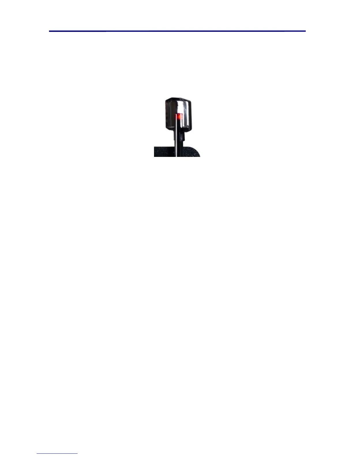
6. Place the OTL parabolic reflector on the infrared detector (see the Figure below)
7. Rotate the parabolic reflector until the locator tone is at a maximum. This is the
direction of the infrared transmitter.
FIGURE 38 IR REFLECTOR
NOTE: There is no need to check for infrared transmitters in rooms without windows. For
rooms with windows, the OSCOR should be placed directly in front of the window to
detect any IR transmitters that may be transmitting through it. Infrared transmitters can
also be placed outside a building and aimed away from it. To defend against this type of
threat, it is necessary to take the OSCOR unit outside and carry it around the perimeter
of the building while scanning for IR threats. On sunny days, the OSCOR IR probe should
be shaded from direct sunlight or bright reflections to prevent overload from the Sun
(direct sunlight will not damage the IR detector).
OSCOR Triangulate and Locate Option
The OSCOR Triangulate and Locate Option (OTL-5000) is designed to locate a
microphone associated with an eavesdropping device. While the OSCOR locator probe
(see page 59 Locating RF (500KHz to 3GHz) Transmitters) is designed to locate the
transmitter antenna, the OTL-5000 option uses sonic ranging to locate the microphone.
The OTL probe hardware includes a piezo clicking device and a parabolic acoustic
reflector that plugs into the OSCOR expansion port.
The OTL-5000 device uses the speed of sound to calculate the range from the
eavesdropping microphone to three independent OTL-5000 positions. The location of
the eavesdropping microphone can be determined using basic triangulation equations
and these measurements in a manner similar to the U.S. Global Positioning system.
NOTE: The OSCOR is not covert in this mode since the OTL-5000 emits a clicking
sound to make range measurements.