73
is lower than usual, then it might be necessary to readjust the coupling of the delivery fiber. To do
so, proceed as described in chapter 4-3, “Optimizing the coupling ratio”
6. Once this coupling is confirmed as good, the output power of the reference laser source should be
within specifications. It is now necessary to check the adjustment of the remaining sources. Proceed
to the next step.
7. If –for example- the source number 2 requires an adjustment, then it will be necessary to fine-tune
the steering elements.
8. Turn on the laser source that requires adjustment. Change your power-meter settings in accordance
with its emission wavelength.
Be sure to wear protective equipment against laser radiation: at this stage, the panel
safety switch should be by-passed (see step 4) and the laser is ready to emit without
restriction.
Keep in mind that the tools used during this procedure will likely cut the beam path
and send scattered light in multiple directions
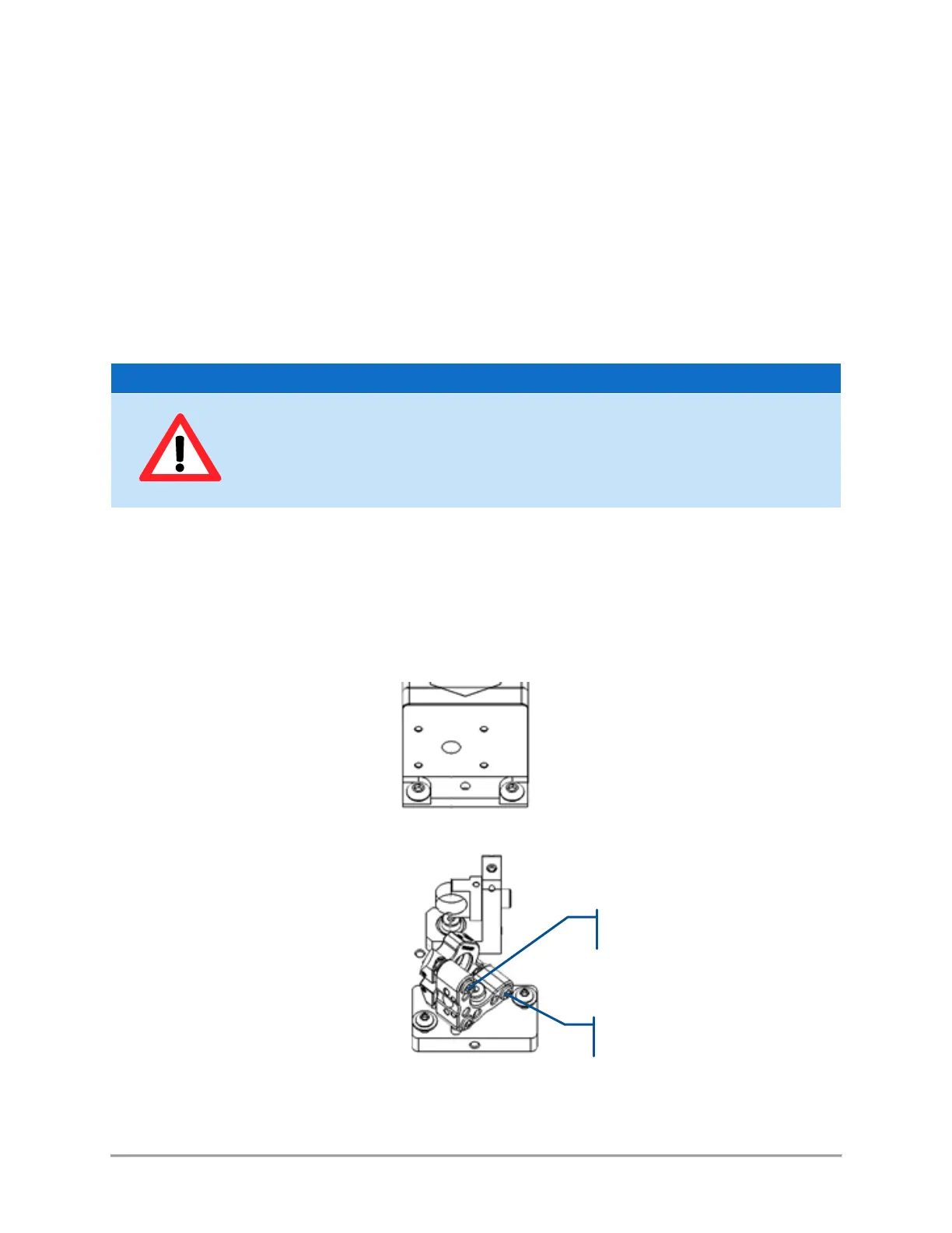
9. Each beam can be first adjusted using its corresponding steering mirror. Two adjustment screws
are used at this purpose: one for steering in the vertical plane (referred to “X” screw), another for
steering in the horizontal plane (referred to “Y” screw). The method consists in adjusting both “X”
and “Y” screws so as to steer the beam back in position.
Figure 8-3: A steering mirror with its “X” and “Y” screws