DigitalFlow™ DF868 Multipurpose Ultrasonic Liquid Flowmeter Programming Manual (2-Channel) 91
Chapter 6. Serial Communications
6.5.3 Multi-Point Wiring
The standard point-to-point wiring configuration for the serial interface converter may be modified to permit the use
of a multi-point wiring arrangement. In a multi-point RS485 system, one flowmeter (the master) is connected to the
personal computer, while a number of additional flowmeters (the slaves) are chained together and connected to the
master flowmeter. In order to implement such a system, the DIP switch settings inside each serial interface converter
must be changed.
IMPORTANT: The serial interface converter in the last
slave unit in the chain should not be reconfigured.
6.5.3.1 Reconfiguring a Serial Interface Converter
To reconfigure a serial interface converter for multi-point wiring, complete the following steps:
1. Disconnect the main power to the electronics console and open the cover.
WARNING! Dangerous voltages exist within the electronics console. Do not perform any wiring operations until
the main power to the unit has been disconnected.
2. Remove the clear plastic shroud that covers the electrical connectors.
3. Remove the serial interface converter mounting bracket by removing the standoff located just below the RS232
terminal block and the grounding screw to its left (see Figure 9 on page 91).
4. Loosen the two screws that fasten the DB9 connector to the mounting bracket, and remove the serial interface
converter from the bracket.
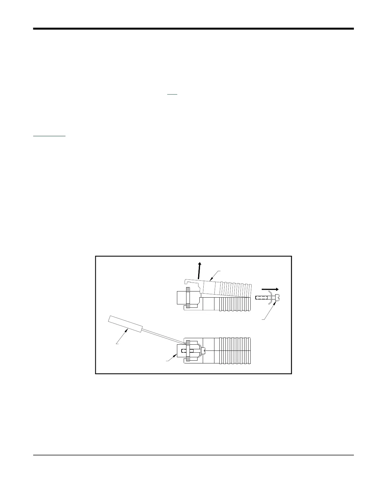
5. Use a small screwdriver to pry open the plastic case of the serial interface converter, as shown in Figure 9 on
page 91.
The serial interface converter contains a main printed circuit board and a daughter printed circuit board. The
daughter board has a small terminal block attached to it and the main board has a DIP switch (SW1) mounted near
the center of the board.
6. Locate the switch assembly on the main board, and move the switch in position 1 from ON to OFF. The standard
ON state for this switch is for point-to-point operation, while the OFF state is needed for multi-point operation.
See Table 40 on page 92 for the proper settings of all four switches on the switch assembly.
Figure 9: Opening the Converter Case
Plastic Case
Mounting Screw
DB9 Connector
Screwdriver