Chapter 1. Programming Site Data
18 DigitalFlow™ DF868 Multipurpose Ultrasonic Liquid Flowmeter Programming Manual (2-Channel)
15. The menu now varies, depending on whether you have activated the TransFlection or Transit-Time mode.
• If you activated the TransFlection mode, the program asks for the Depth of Reflector. This setting determines
where in the pipe the DF868 looks for the reflected signal. The default value is 50%. Use the numeric keys to enter
a value, and press [ENT].
Note: The factory recommends activating the Reynolds Correction Factor when the Depth of Reflector is set at
50%. You can disable the Reynolds Correction Factor when the Depth of Reflector is set at any other value.
• If you activated the Transit-Time mode, two steps appear.
a.
Use the [F1]-[F4] keys to select the desired Number of Traverses, the number of times the ultrasonic signal
traverses the pipe, from 1 to 5.
b. The Transducer Spacing prompt displays the spacing of the transducers, as calculated from the information
you have entered. Record this number and use it to properly space transducers.
Note: If necessary, you can overwrite the spacing shown (using the numeric keys) to match the actual physical
spacing of the transducers. The factory does not recommend overwriting the spacing. If you must, do not
change the spacing by more than ±10% from the value shown.
You have completed entering pipe parameters for clamp-on transducers. Press [ENT] to return to the start of the
PIPE submenu, and [EXIT] to leave the submenu. Table 11 lists the numeric parameters in the PIPE submenu, with their
high and low limits.
1.6.4 Setting Up Inputs/Outputs
The following specific tasks may be performed via the I/O submenu:
• Enter a zero cutoff value to eliminate low flow reading fluctuations
• Set up any temperature input supply and return for the Energy Option, or the fluid temperature input for
Temperature Compensation
While following the programming instructions, refer to the menu map in Figure 12 on page 99. Remember to record all
programmed data in Appendix B, Data Records.
1. To enter the Channel PROGRAM menu, press [F1] or [F2] (depending on the desired channel) at the User
PROGRAM prompt.
2. Enter the I/O submenu by pressing [F4] at the Channel PROGRAM prompt.
1.6.4.1 Zero Cutoff Value
3. Enter the desired Zero Cutoff value and press the [ENT] key. A value of 0.1 ft/s (0.03 m/s) is recommended, but
values from 0–1 ft/s (0–0.3 m/s) are acceptable.
If you have not enabled the Energy Option in the SYSTEM submenu or a Viscosity Table in the ADVAN submenu, the
DF868 returns to the Channel PROGRAM prompt. But if you have enabled the Energy Option, the input supply and
return prompts let you specify either live or fixed supply and return temperature inputs for the energy flow
calculation. If you have enabled a temperature vs. viscosity table, the fluid temperature prompt lets you specify a live
or fixed temperature input.
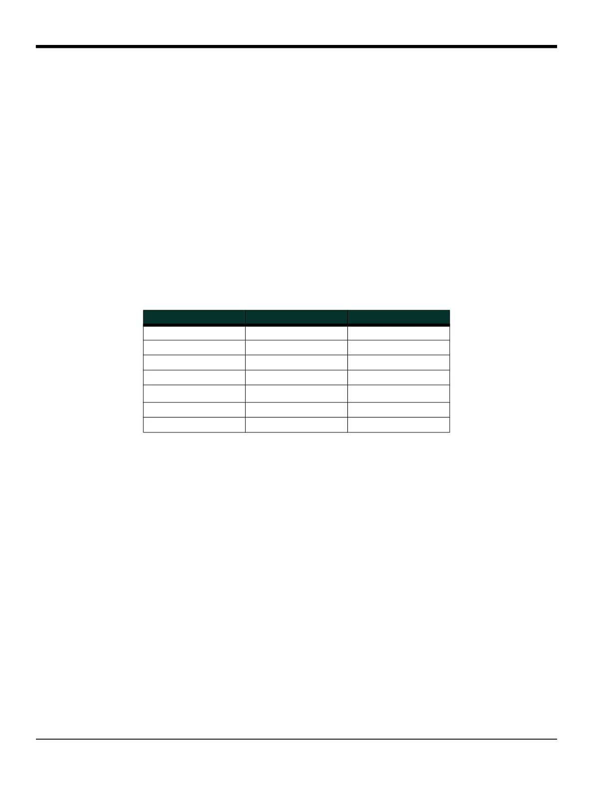
Table 11: Low and High Limits for PIPE Parameters
Parameter Low Limit High Limit
Wedge Angle 25° 90°
Pipe OD 0.12 in. 300 in.
Pipe Wall 0 in. 4.0 in.
Lining Thickness 0 in. 4.0 in.
Kinematic Viscosity 0.1
10,000 (E-6 ft
2
/s)
Path Length 0.12 in. 480 in.
Axial Length 0.12 in. 480 in.