12-23
(A: Available, N/A: Not available)
Register
No.
Name Descriptions
Read
-ing
Writ-
ing
DT90022
Scan time (current
value)
Note)
The current scan time is stored here. Scan
time is calculated using the formula:
Scan time (ms) = stored data (decimal) x 0.1
ms
Example: K50 indicates 5 ms.
AN/A
DT90023
Scan time (minimum
value)
Note)
The minimum scan time is stored here. Scan
time is calculated using the formula:
Scan time (ms) = stored data (decimal) x 0.1
ms
Example: K50 indicates 5 ms.
AN/A
DT90024
Scan time (maximum
value)
Note)
The maximum scan time is stored here. The
scan time is calculated using the formula:
Scan time (ms) = stored data (decimal) x 0.1
ms
Example: K125 indicates 12.5 ms.
AN/A
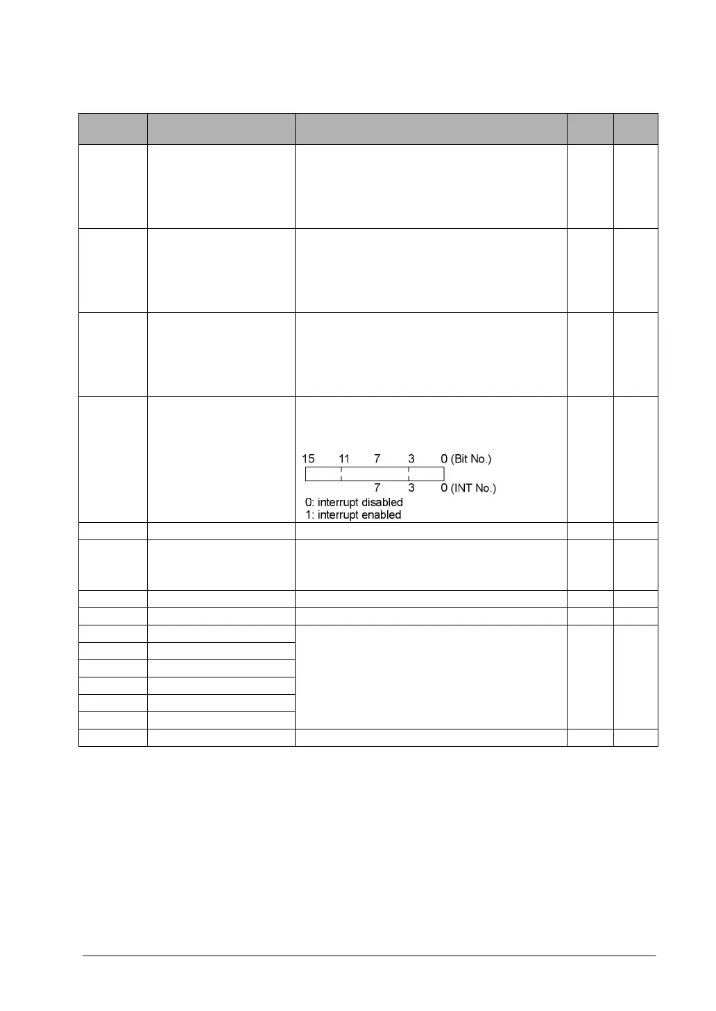
DT90025
Mask condition
monitoring register
for interrupts
(INT0 to 7)
The mask conditions of interrupts using the
instruction can be stored here. Monitor using
binary display.
AN/A
DT90026 Not used N/A N/A
DT90027
Periodical interrupt
interval (INT24)
The value set by ICTL instruction is stored.
K0: periodical interrupt is not used.
K1 to K3000: 0.5ms to 1.5s or 10ms to 30s
AN/A
DT90028 Not used N/A N/A
DT90029 Not used N/A N/A
DT90030 Message 0
DT90031 Message 1
DT90032 Message 2
DT90033 Message 3
DT90034 Message 4
DT90035 Message 5
The contents of the specified message (Data
lenght) are stored in these special data
registers when F149 (MSG) instruction is
executed.
AN/A
DT90036 Not used N/A N/A
Note) Scan time display is only possible in RUN mode, and shows the operation cycle time. (In PROG.
mode, the scan time for the operation is not displayed.) The maximum and minimum values are
cleared earh time the mode is switched from RUN to PROG.