FP Modem-EU Technical Manual
3.4 Steps for Establishing and Terminating a Connection
3.4 Steps for Establishing and Terminating a Connection
If the modem is in data mode, you can get back to the command mode with the Escape
command +++ (without AT!). You can switch back to the data mode with ATO.
Controller and modem are ready for operation (Power LED is on.) The external telephone cable
has been connected to the telephone jack (e.g. the TAE socket for Germany). The procedure
will be explained for a telephone connection at a subscriber’s station with tone dialing.
3.4.1 Establishing a Connection
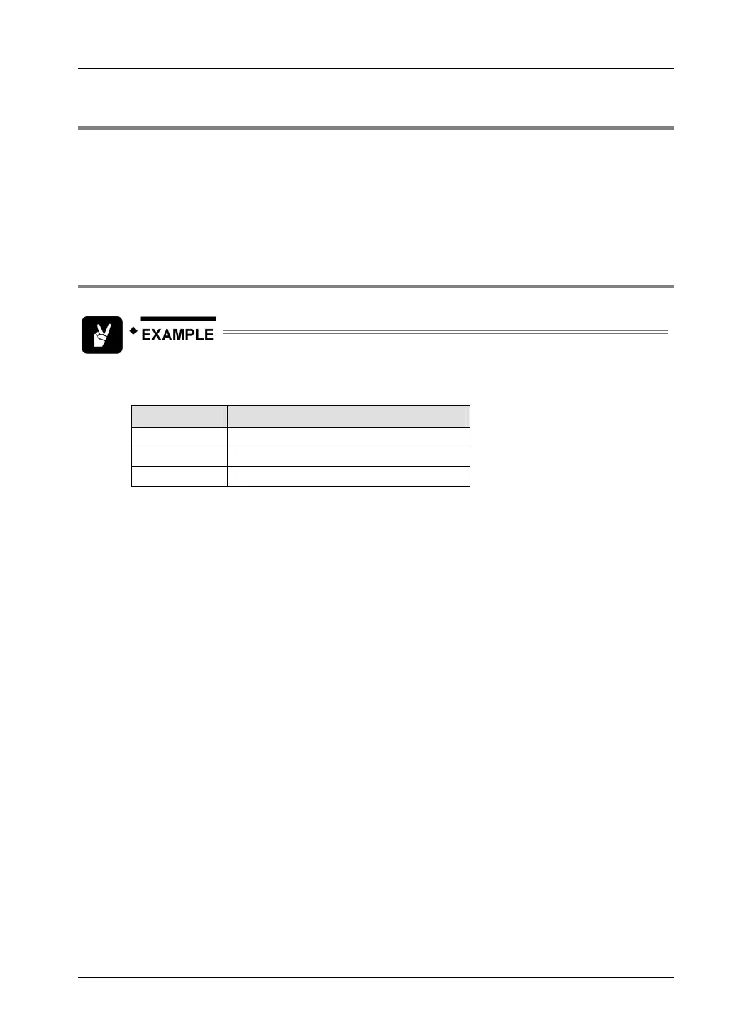
The controller sends ATDT099912345<CR> to the modem. The end code carriage
return is hexadecimal 0D.
Signal Meaning
AT initiate command
DT dial with tone dialing
099912345 telephone number being called
The modem starts dialing. After the subscriber’s station answers, the handshaking protocol
between the two modems is carried out. Therein, the type of modulation, the line transmission
speed and the used protocols are agreed upon. If the connection was established successfully,
the modem optionally reports the line speed, the type of error protocol used and the RS232C
baud rate to the controller. After that the modem switches to data mode. The DCD LED lights up
and the DCD output switches to the active state.
In data mode, the modem transmits information to be exchanged directly from the controller to
the remote modem or vice versa.
The data connection cannot be established if the two modems cannot detect a transmission
method that can be used by both, or if extremely severe interference occurs. The modem
responds with NO ANSWER, or if the distant modem is busy, the modem responds with BUSY.
When the modem is called, it will send the ASCII string RING to the controller at every ring. If a
number higher than zero has been adjusted in the S0 register, the modem answers
automatically after the expiration of this preset number of rings. Now the handshaking protocol
starts, as described above.
With S0=0, the modem remains in an inactive state. The connection can be established with the
ATA command as soon as RING has been recognized.
35

 Loading...


