Hardware Installation
FP Modem-EU Technical Manual
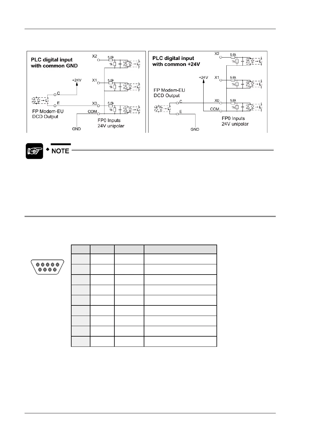
Wiring Diagram
The 24V digital signal is needed because the RS232C interface of the Panasonic
PLC does not support handshake or modem control lines. The connect status
message NO CARRIER (via RS232C) cannot be reliably detected during a data
communication connection.
2.7.3 RS232C Cables
RS232C data interface
Pin Name Direction Description
1
DCD
→
Carrier Detect
2
RXD
→
Receive Data
3
TXD
←
Transmit Data
4
DTR
←
Data Terminal Ready
5
GND
→
System Ground
6
DSR
→
Data Set Ready
7
RTS
←
Request To Send
8
CTS
→
Clear To Send
51
96
Sub-D 9 female
9
RI
→
Ring Indicator
PLC-Modem
For the connection to the PLC (especially the Tool port), automatic baud rate detection should
be disabled using AT*W (see "
Command Tables" on page 68).
26

 Loading...


