2.1 Names and Functions of Parts
2.1.1 Communication Port of CPU Unit
(In the above figure, a communication cassette is attached to the COM.1 and COM.2 ports.)
■
Names and Functions of Parts
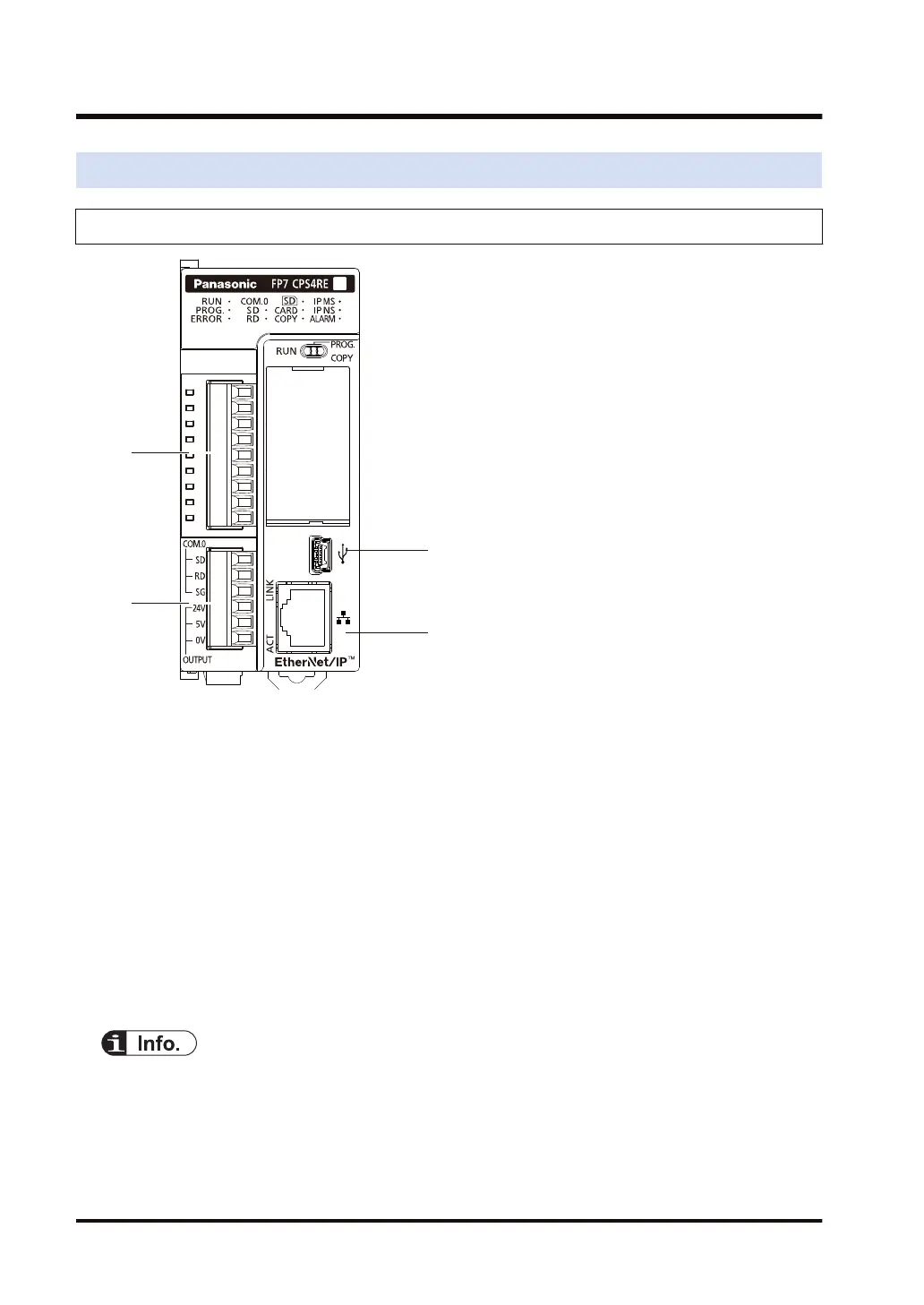
(1) COM.1 and COM.2 ports
Attach a separately sold communication cassette to use these ports. A blank cover is fitted
when the unit is shipped.
(2) COM.0 port, GT power supply terminals
This is an RS-232C port that is equipped to a standard model of CPU unit. It is equipped with
power supply terminals (5V DC and 24V DC) to which a GT series programmable display can
be connected.
(3) LAN port
This is equipped to a standard model of CPU unit. This is used for connection to Ethernet.
(4) USB port
This is equipped to a standard model of CPU unit. This is used for connecting tool software.
● For details of the communication method using LAN port, refer to FP7 CPU Unit User's Manual
(LAN port communication).
● For details of the communication using Communication cassette (Ethernet type)
AFP7CCRET1, refer to FP7 series User's Manual (Communication cassette Ethernet type).
2.1 Names and Functions of Parts
2-2 WUME-FP7COM-07

 Loading...


