Outpu
t
signal
Communication
port
Name Description
Effective
operation
mode
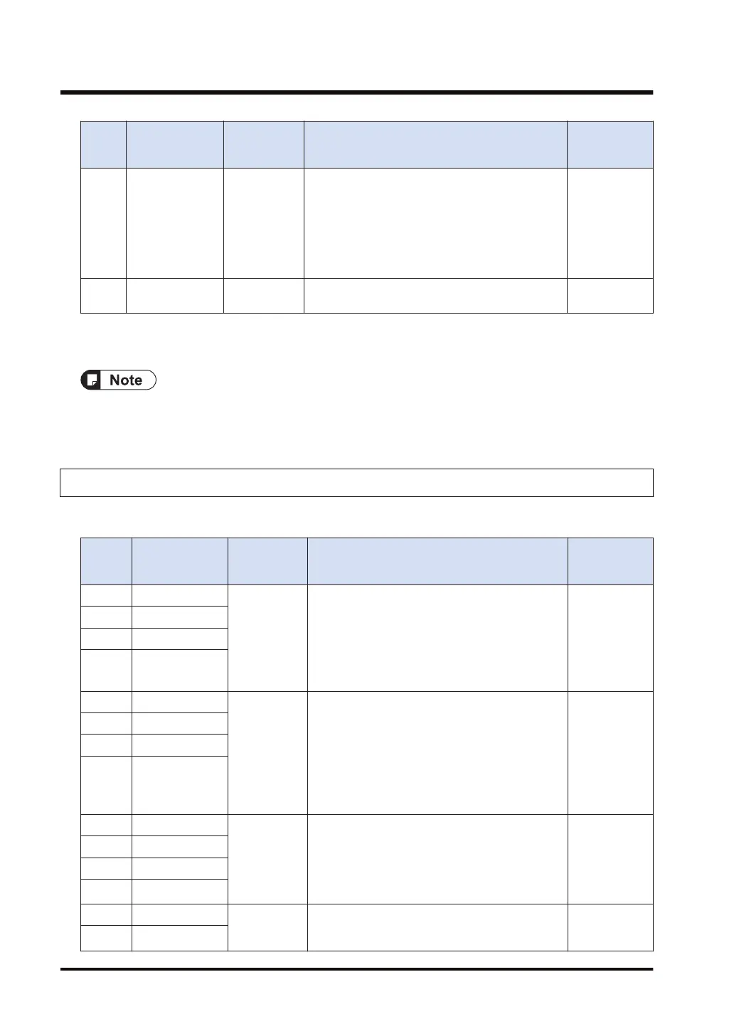
Y14 For COM.1 Port
Output RTS
signal
By turning on (1) this output, RTS is controlled.
Transmission from the device communicating with
is permitted = 0
Transmission from the device communicating with
is prohibited = 1
Monitor the CTS signal from the device
communicating with using X14.
When RS/CS
is set to valid
in
communication
Cassette
COM.1
Y15 to
Y1F
- Undefined Do not turn on "undefined". (Default setting is 0.)
(Note 1) When transmission is completed within one scan, it turns off when the GPSEND instruction is
executed in the subsequent scan.
● Each contact in the table above is used for reading the operation status. Do not write over it
with a user program. (excluding Y10 - Y12 and Y14)
4.1.2 I/O Allocation of Serial Communication Unit
■
Input signal
Input
signal
Communication
port
Name Description
Effective
operation
mode
X0 For COM.1 Port General-
purpose
communicatio
n
Reception
done
flag
When the unit completes the data reception, it
turns on (1).
Waiting for data reception: 0, Reception
completed: 1
General-
purpose
communicatio
n
X1 For COM.2 Port
X2 For COM.3 Port
X3 For COM.4 Port
X4 For COM.1 Port General-
purpose
communicatio
n
Reception
done
(copy)
flag
It turns on (1) if there are copied data when
GPRECV instruction is executed. It turns off (0)
when END instruction is executed.
(Note 1)
Reading completed: 1
No data to be read: 0
General-
purpose
communicatio
n
X5 For COM.2 Port
X6 For COM.3 Port
X7 For COM.4 Port
X8 For COM.1 Port General-
purpose
communicatio
n
Clear to send
flag
It turns on (1) when the unit is set to the general-
purpose communication mode. It turns off (0) in
other modes.
General-
purpose
communicatio
n
X9 For COM.2 Port
XA For COM.3 Port
XB For COM.4 Port
XC For COM.1 Port
Master
communicatio
n
It turns on (1) when the unit is set to modes other
than the PLC link mode or general-purpose
MEWTOCOL
MODBUS
RTU
XD For COM.2 Port
4.1 Input/Output Signals Used for Communication
4-4 WUME-FP7COM-07

 Loading...


