■
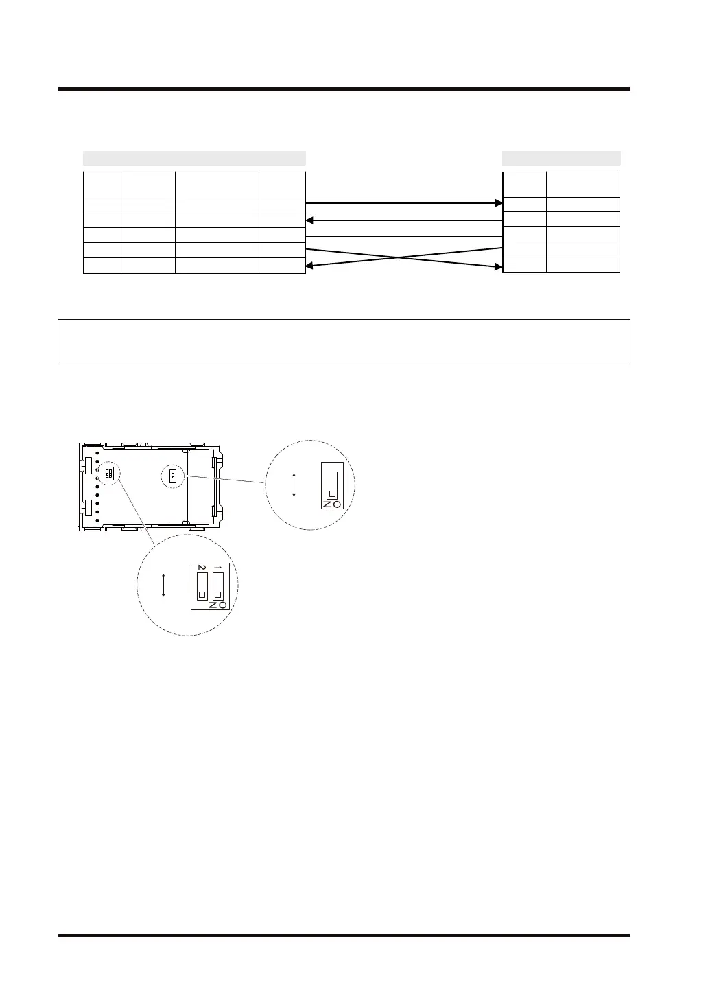
Example of wiring (in the setting of 5-wire 1-channel RS-232C RS/CS controlled)
AFP7CCRS2
Termina
l No.
Terminal
part symbol
Signal name Functions
1 SD Sent Data SD
2 RD Received Data RD
3 SG Signal Ground SG
4 SD Request to Send RS
5 RD Clear to Send CS
Partner
Symbol Signal name
RD Received Data
SD Sent Data
SG Signal Ground
RS Request to Send
CS Clear to Send
3.4.3 Communication Cassette AFP7CCRM1 (RS-422 / RS-485, 1-Channel
Insulated Type)
■
Setting of application switch
Applications for use can be switched using a switch on the backplane for Communication
Cassette AFP7CCRM1. Settings can be confirmed with LED lamps at the front of the cassette.
(Note 1) The switch is factory-set to RS-485.
■
Settings for termination resistance selector switch
On the surface of Communication Cassette AFP7CCRM1 is located a termination resistance
selector switch.
● When RS-422 is used: Turn ON the switch.
● When RS-485 is used: Turn ON the switch only when it is the end unit.
3.4 Wiring for Communication Cassettes COM.1 to COM.4 Ports
3-12 WUME-FP7COM-07

 Loading...


