■
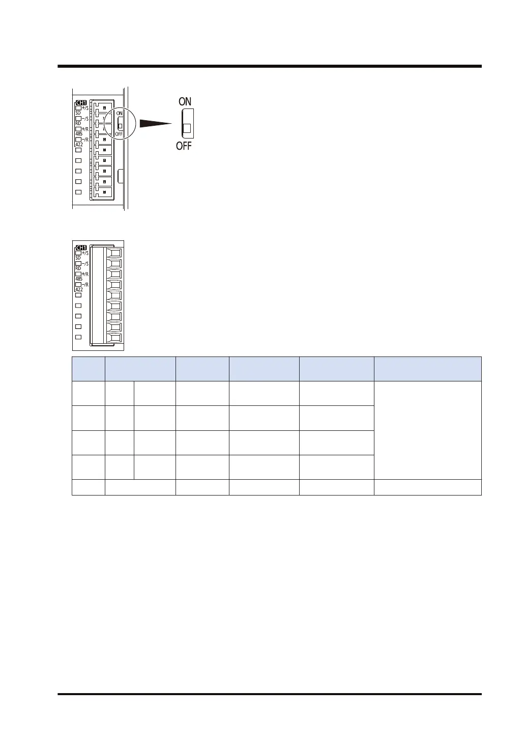
Terminal layout (in the setting of RS-485)
Termin
al no.
LED part
symbol
Terminal
part symbol
Functions that
can be allocated
Signal direction
Ports that can be
allocated in the software
1 CH1 SD + / S
Transmission line
(+)
-
COM.1/COM.3
2 RD
- / S Transmission line
(-)
-
3 485
+ / R Transmission line
(+)
-
4 422
- / R Transmission line
(-)
-
5 to 9 - - - - -
(Note 1) In the setting of RS-485, Terminal No.1 and Terminal No.3, and Terminal No.2 and Terminal No.4 are
respectively connected inside. They can be used as terminals for crossover wiring for the transmission
cable.
(Note 2) Do not connect anything to Terminals No.5 through No.9.
3.4 Wiring for Communication Cassettes COM.1 to COM.4 Ports
WUME-FP7COM-07 3-13

 Loading...


