Structure of a link area
6.3.4 Ranges of Link Relays and Link Registers to be Used
● Specify the ranges of memory areas of link relays and link registers to be actually used.
● Link relays and link registers that are not to be used for linking may be used in place of
internal relays and data registers.
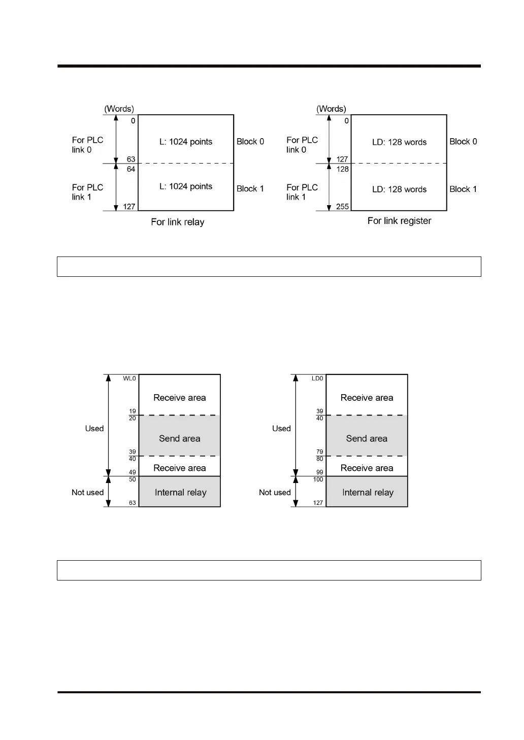
Example) Setting of ranges for use (in the case of PLC link 0)
● The diagram below indicates a case when “50” (50 words from WL0 to WL49) is specified for
the range of link relay, and “100” (100 words from LD0 to LD99) for the range of link register
to be used.
● As the range to be used in PLC link 0, specify “64” (64 words) when all link relays are to be
used, and “128” (128 words) when all link registers are to be used.
6.3.5 Link Relay Transmission Start Number and Sending Size
● The memory areas of link relays are divided into send areas and receive areas.
● Link relays are transmitted from the send area of a PLC to the receive area of another PLC.
The receiving PLC must have the same link relay No. in its receive area as the sending PLC.
6.3 Setting Items for PLC Link
WUME-FP7COM-07 6-9

 Loading...


