8.4 MODBUS RTU Master Communication (SEND)
8.4.1 Write Data into an External Device
■
Instructions
In master communication, PLC has the sending right, and executes communication by sending
commands to devices that support MODBUS RTU, and receiving responses. Messages in
accordance with the protocol are automatically generated by PLC. In the user program, reading
and writing can be done simply by specifying the station no. and memory address and
executing SEND/RECV instructions.
■
Sample program
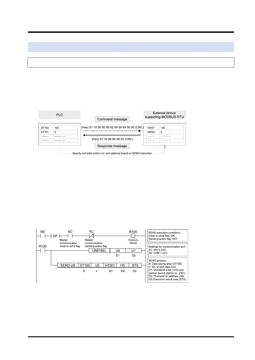
● Send commands from the COM.1 port of the CPU unit, and write the content of PLC's data
register DT100 - DT101 into the data area of an external device (station no. 1) 40001 -
40002.
● Confirm that the unit is in the master mode (XC), and that the sending process is not in
progress for the same port (YC), and start up the SEND instruction.
● In the UNITSEL instruction, specify the slot No. (U0) and the COM. port No. (U1).
● In the SEND instruction, specify and execute the PLC initial address (DT100), No. of data
(U2), MODBUS function code to be used (16: H10), partner device station no. (H01), and
initial address (H0). For the address of the partner device, please check operating
instructions, etc. of the relevant device.
(Note 1) Operand [D1] of SEND instruction is specified by combining two hexadecimal digits of MODBUS
function code with two hexadecimal digits of partner device station no. When the MODBUS function
code is 16, [D1] H10 should be specified.
(Note 2) When the partner device is FP series PLC, Operand [D2] of SEND instruction can be specified using
the device no.
(Note 3) The unit number and COM. port number in the above program is applied when the COM.1 port of the
CPU unit is used.
8.4 MODBUS RTU Master Communication (SEND)
WUME-FP7COM-07 8-21

 Loading...


