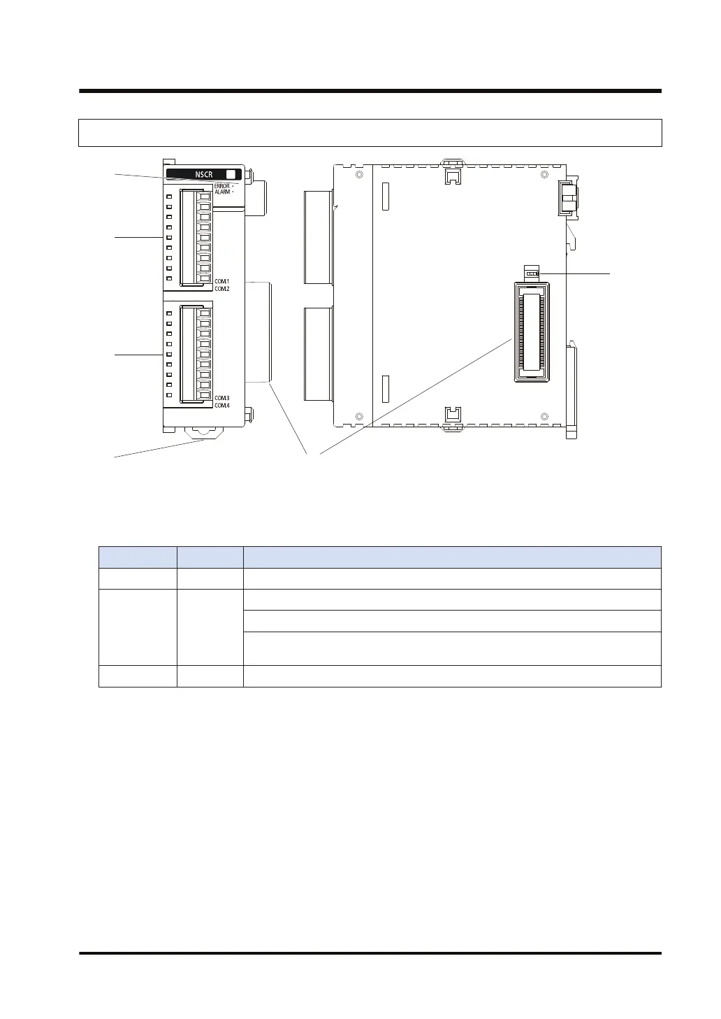
2.1.2 Parts Names and Functions of Serial Communication Unit
(In the above figure, two communication cassettes are attached.)
■
Names and Functions of Parts
(1) Operation monitor LEDs
Display LED color Description
- Blue Lights when the power supply of the CPU unit is on.
ERROR Red
Lights when the configuration setting is incorrect, or a communication error occurs.
Flashes when the factory acceptance test switch is on. (Flashing cycle: 100 ms)
Flashes when an extension cassette that cannot be used is installed. (Flashing
cycle: 500 ms)
ALARM Red Lights when an error occurs in hardware.
(2) COM.1 and COM.2 ports
Attach a separately sold communication cassette to use these ports. No blank cover is fitted
when the unit is shipped.
These ports differ from the COM.1 and COM.2 ports of the CPU unit.
(3) COM.3 and COM.4 ports
Attach a separately sold communication cassette to use these ports. A blank cover is fitted
when the unit is shipped.
(4) DIN hook
This is used to fix the unit to a DIN rail.
(5) Unit connector
This is used to connect the internal circuit of an I/O unit or advanced unit.
(6) Factory acceptance test switch
This is used for factory acceptance test. Do not turn it on.
2.1 Names and Functions of Parts
WUME-FP7COM-07 2-3

 Loading...


